I’m working on a project using an ESP32 to control a 12V contactor, with a W5500 Ethernet module for internet connectivity. The issue I’m encountering is that the ESP32 either restarts or loses its network connection whenever the contactor is switched on or off.
Project Setup:
ESP32 controlling a 12V contactor via a transistor-based driver circuit using the ULN2003A IC.
W5500 Ethernet module for network communication.
Powering the ESP32 and W5500 from a 5V buck converter that steps down from a 12V SMPS, which also powers the 12V contactor.
The ULN2003A has built-in flyback diodes for inductive load protection.
I’ve added 2 x 470µF capacitors and 2 x 100nF capacitors to stabilize the power supply for the ULN2003A.
The Problem:
Whenever the 12V contactor switches (on or off), the ESP32 restarts or loses its network connection. I suspect this is due to either EMI from the contactor or voltage transients affecting the power supply shared with the ESP32.
What I’ve Done So Far:
Decoupling Capacitors: Added decoupling capacitors (10 µF, 100 µF, 0.1 µF) near the power pins of the ESP32 and W5500.
Separate Power Rails: The 12V SMPS powers both the contactor and the ESP32/W5500 via a 5V buck converter.
Optocoupler Isolation: The contactor driver circuit is isolated from the ESP32 via an optocoupler.
Built-in Flyback Diodes: The ULN2003A IC has built-in flyback diodes to protect against voltage spikes from the contactor coil.
Additional Filtering for ULN2003A: Added 2 x 470µF capacitors and 2 x 100nF capacitors to stabilize the power supply for the ULN2003A IC.
My Questions:
Since the ULN2003A has built-in flyback diodes, is this protection sufficient, or should I consider adding an external flyback diode for extra reliability?
How can I further reduce the effect of contactor switching transients on the ESP32 and W5500?
Would adding a snubber circuit across the contactor coil help with this problem?
Should I consider isolating the power supplies for the ESP32/W5500 and the contactor, or are there other ways to mitigate this interference?
Thanks in advance for your help! I’m looking for advice on how to handle these power or EMI issues more effectively.
I moved your topic to a more appropriate forum category @atiiot .
The Nano ESP32 category you chose is only used for discussions directly related to the Arduino Nano ESP32 board.
In the future, please take the time to pick the forum category that best suits the subject of your question. There is an "About the _____ category" topic at the top of each category that explains its purpose.
If your hypothesis is correct that this may be power sag/brownout, then you want to stabilize the esp power supply. Have you tried a big buffer capacitor on the 5V rail? Let's say 1000uF or 2200uF or so.
Also, we're stumbling in the dark w.r.t. the cause of the problem; do you have a scope that you can use to see what happens in various places when the contractor switches?
PS: the combination of an esp32 and an uln2003 is an interesting juxtaposition of eras - the 1980s meet the 2020s. It should work in principle.
PPS: where's the data on the 12V contactor so we can see what it's drive requirements and possible impact on the rest of the system are? Also, what does the contactor switch ?
There's a good chance that this would be an effective workaround. Although I can see why he'd prefer to have a single supply for the entire thing, which in principle should be possible
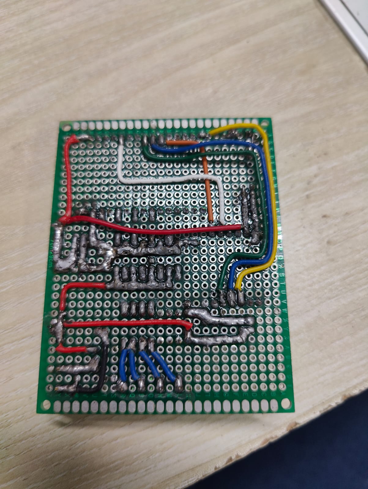
@atiiot also missing is any data on your 12V power supply and a schematic of your project. The wiring looks tidy; I'm not too worried about that.
I’ve checked my connections multiple times to ensure there are no shorts, and I also performed continuity tests without finding any issues. The setup works as intended most of the time, but I experience occasional restarts or disconnections of the ESP32 when the contactor switches.
Here is my schematic diagram of the circuit for reference.
I can definitely consider using a separate power supply for the ESP32. However, is there something I can do to resolve the issue while still using the same power supply? I’d like to avoid adding another supply if possible, but I’m open to any tips for stabilizing the current setup with the shared 12V SMPS.
About wires and EMI.
Any wire is an antenna (both sending and receiving).
Two parallel wires (a bundle) with opposite current will generate fields that cancel out.
Also works with pickup of emi. Two parallel wires will pickup the same interference. Therefore the picked up interference cancels out. If two wires are far apart, one might pick up more emi than the other. No cancellation...
Instead of setting the buck-converter to 5v and connecting it to the esp32 5v pin, you can also set it to 3.3v and connecting it to the esp32 3.3v pin bypassing the 3.3v regulator on the esp32. No guarantee but you don't actually use 5v and the onboard regulator may be part of the problem.
These diodes protect ULN2003 by sending voltage spikes to vcc... ...hoping that they will be buffered there... ...high voltage spike may leak to esp... try to feed esp from battery. See if that solves the problem... if so: find a better way to power esp...
Something I have done a few times is use a buck converter to take 12VDC down to 7ish then feed that to a LDO VR to deliver the 5VDC. I don't have any huge engineering reason, I just thought that arrangement got the best of both worlds and you can stick with the single 12VDC power supply.
Can you please post a copy of your circuit, a picture of a hand drawn circuit in jpg, png?
Hand drawn and photographed is perfectly acceptable.
Please include ALL hardware, power supplies, component names and pin labels.
Rather than a cut and paste.
Do you have 4 of these contactors.
Can you please post specs/data on the contactor you are controlling?
Can you please post the specs/data of the 12V supply?
12V SMPS (2A) power supply, which is used to power the contactors.
LM2596 adjustable power supply, used to power my ESP32 and W5500 Ethernet module.
The contactor I’m using is the Kincony BCH8 25Z AC contactor with the following specifications:
Yes i am using 4 contactors
Maximum Load Current: 25A
Rated Voltage: AC 220V
Phase: Single-phase power load, designed for AC 220V applications
It’s typically used in home automation systems and can be integrated with Kincony’s smart relay controllers. It often requires an RC snubber to handle inductive loads.
Regarding the specific capacitors, I used them because I was following someone else's schematic, which included these decoupling capacitors. I’m kind of new to electronics, so I’m not sure if this capacitor is useful or harmful in my circuit.
I did check the power supply to the ESP32 using an oscilloscope when switching occurred, and I didn’t see a dip, so I didn’t add any large capacitors at that time. However, I can still add a big capacitor like 1000uF or 2200uF if you think that could help stabilize the power supply.
Here are the specifications of the contactor:
Kincony BCH8 25Z AC contactor:
Maximum Load Current: 25A
Rated Voltage: AC 220V
Phase: Single-phase power load, designed for AC 220V applications
Typically used in home automation systems and integrated with Kincony’s smart relay controllers.
The contactors are used to switch 220V LED lights and an exhaust fan as part of my home automation project.
As for the 12V power supply, I’m using a 12V 2A SMPS power supply (model RS-25-12) with the following specifications:
Power rating: 25W
Protection features: Overload, Short Circuit, Over Voltage Protection
Input Voltage: 100-120VAC / 200-240VAC
This power supply is used for the contactors, while an LM2596 adjustable power supply is used to power the ESP32.
Thanks again for your input, and I’d appreciate any further suggestions on stabilizing the system without adding a separate power supply.
Thanks for the suggestion! But could you explain what the benefit of doing that would be, aside from bypassing the onboard regulator? I'd like to understand how it might help with my issue.