I used to be able to work with my ESP8266 a couple months ago, but when I tried to play around with it again today, I noticed that the Arduino IDE now has a billion options in the tools menu when you select ESP8266 as your board:
I could not get the old sketch successfully re-uploaded to the ESP. I am grounding the appropriate pins, the sketch does upload (the IDE progress bar goes to 100%) but the ESP8266 does not work and just returns jibberish on the serial monitor (tried every baud rate).
The ESP was working fine today before I tried to re-upload a sketch.
So I assume some of the settings are off and I need to fix them, but I can't find info about them anywhere. I used to have to set the programmer to esptool but that's no longer an option either, apparently it is supposed to be set behind the scenes automatically now.
Does anyone here have any idea how you're supposed to upload sketches to a ESP8266 now?
I hate it when an update just comes around and breaks your existing projects.
If its an 01 there are also a couple of types as they upgraded them.
There is also an ESP config checker sketch in the ESP examples.
Some may also need to be reflashed (had a batch that needed it as they had older firmware on them)
A pic would be nice too of the ESP itself.
EDIT
If you are going to blow the newer firmware make sure you know what the settings for the ESP are for memory etc.
It doesn't brick them but it will mean you have to do it again.
There are plenty of topics on google for "bricked" ESP's and almost all of them come back to life.
Sorry, I forget that "ESP8266" is a term that encompasses all the models. It's an ESP-01. One of these:
I'd rather not flash the firmware because as I said it was working perfectly fine a few months ago (and still was today, until I tried to upload a new sketch). I think I just need to figure out what settings I need to use.
I'll see about the ESP config checker in the examples, though I'm not sure how it would work if I can't get it uploaded properly to the device.
Most the the black ones (not all) tend to be the upgraded ones.
Not seen any definitive markings on most of mine and would need the Hubble telescope to read the chip LOL.
Just reloaded my ESP stuff to check for you.
Good too as there was a package update so thanks !
IDE 1.8.1
Boards 2.3.0 (under esp8266)
Select "Generic ESP8266 Module"
Select the correct COM port for your programmer.
Make sure your jumper/switch or whatever else you use for upload is in place !
Goto EXAMPLES
Find ESP8266
Select "CheckFlashConfig"
Upload
Disconnect the ESP from the computer (unplug programmer)
Swap your jumper/switch etc. back to its normal position.
Open Serial Monitor in IDE
Re-connect to computer
(IGNORE and early garbage as its similar to BIOS stuff and is usually at an odd baud rate)
You should then get a display of the correct settings or a passed
Flash real id:   001440E0
Flash real size: 1048576

Flash ide  size: 524288
Flash ide speed: 40000000
Flash ide mode:  DIO
Flash Chip configuration wrong!

Flash real id:   001440E0
Flash real size: 1048576

Flash ide  size: 524288
Flash ide speed: 40000000
Flash ide mode:  DIO
Flash Chip configuration wrong!
ETC etc.
Or if Correct
Flash ide  size: 1048576
Flash ide speed: 40000000
Flash ide mode:  DIO
Flash Chip configuration ok.

Flash real id:   001440E0
Flash real size: 1048576

Flash ide  size: 1048576
Flash ide speed: 40000000
Flash ide mode:  DIO
Flash Chip configuration ok.

Flash real id:   001440E0
Flash real size: 1048576

Flash ide  size: 1048576
Flash ide speed: 40000000
Flash ide mode:  DIO
Flash Chip configuration ok.
Open Serial Monitor 115200
BTW I use "CoolTerm" as its very easy to use and has a ton more options than the serial monitor so its also handy with the RasPi.
Make sure you are using a programmer that does not put out any more than 3.3 V to the supply pin or there is a good chance to pop them little esp suckers and let out the magic smoke.
TX - RX
RX - TX
GND - GND
VCC - VCC
100% working here, Wrote this as I did it so know that if you have an issue it maybe time for you to double check everything.
BTW do you have a cap across VCC and GND as I use one on all my ESP 01's
Thanks a lot for the detailed response, I'll try it now and see how it goes.
The cap was actually going to be a followup question, thanks for reminding me. Does it matter what value of cap I use? (I have some 16V 10uF and 25V 100uF ones).
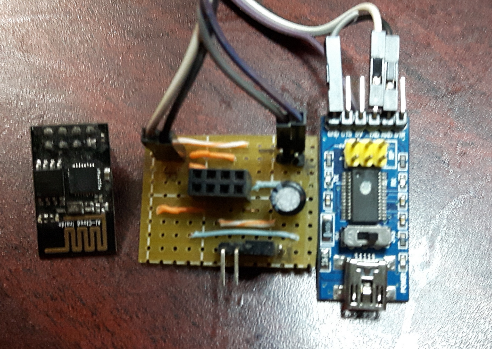
Edit: This is my setup. I guess this is where I need to add the capacitor? (with the correct polarity ofc)
Edit2: I ran the CheckFlashConfig sketch and this is the result I got:
Flash real id:   001440E0
Flash real size: 1048576

Flash ide  size: 524288
Flash ide speed: 40000000
Flash ide mode:  DIO
Flash Chip configuration wrong!
Not sure what I'm supposed to do with this result though? Do I need to just change settings randomly and re-upload until it says the configuration is okay?
Flash Mode = DIO
Flash Frequency = 40 Mhz ( Can be overclocked on some modules )
CPU Frequency = 80 Mhz ( See note above )
Flash Size = 1M (512k SPIFFS) <<< The important one
Debug port = disabled
Debug level = none
Reset Method = ck
Upload speed = 115200
Those are my settings for esp8266 ( 01's)
The cap provides buffer power in a TX phase so size will be slightly dependant on the amount of TX time.
Have 2 with 10uF and one with 100 uF and all work reliable sending a single sensor bit of data to THINGSPEAK.
You can go higher if you need but remember to keep them around the 5 to 25 V range Going lower might be a little unreliable and higher would probably be a waste of board space.
Thanks a lot for the help. I initially couldn't get it working with the increased flash size either, then I started digging into more and more guides telling me to do all kinds of things like putting pull-up resistors on CH_PD, GPIO0, GPIO2, connecting FTDI-DTR to GPIO0, etc etc. I spiraled deeper and deeper into madness as the errors got more and more ridiculous with everything I tried.
At the end, I just scrapped all that, put everything back how it was, and added an external power supply. At first this didn't work either. But then I realized I still need to keep the FTDI's VCC & GND connected as well, and finally I got it working again!
So in short, I guess the problem was a lack of power as well as incorrect flash size. I hope this helps anyone else who stumbles into this issue. (The FTDI power works fine for brief periods but both the ESP and the FTDI get really hot after a minute or so, and then the serial data starts getting corrupt and the ESP starts resetting).
Yeah it's an FTDI with a switch. It's in 3V3 mode. I just double checked it with a multimeter and it is indeed outputting 3.3v. I'm pretty sure the ESP would have popped already if it was outputting 5V.
Is that a two pin jumper you are using to switch the ESP between regular and programming mode?
Have lots from computer work so seemed a good idea to be able to use them.
Know its not pretty but I can replicate them quite easily now I have a pattern so to speak.
Have room for a couple more components if I need but so far all I do is program them,swap jumper,add sensor and away to deploy with a suitable old 3V (3.2-3.6) phone charger or similar I pick up at the thrift shops for pennies.
ballscrewbob:
My bad sorry for not adding what I use
OK here is what works well for me.
Flash Mode = DIO
Flash Frequency = 40 Mhz ( Can be overclocked on some modules )
CPU Frequency = 80 Mhz ( See note above )
Flash Size = 1M (512k SPIFFS) <<< The important one
Debug port = disabled
Debug level = none
Reset Method = ck
Upload speed = 115200
Those are my settings for esp8266 ( 01's)
The cap provides buffer power in a TX phase so size will be slightly dependant on the amount of TX time.
Have 2 with 10uF and one with 100 uF and all work reliable sending a single sensor bit of data to THINGSPEAK.
You can go higher if you need but remember to keep them around the 5 to 25 V range Going lower might be a little unreliable and higher would probably be a waste of board space.
For ESP8266 12E or 12F: flash size is 4M (1M SPIFFS)

