I have a real newbie rookie question and I really hope somebody out there is able to give some useful directions to help me out.
I'm currently working on an interactive project where I'm using analog sensors, an Arduino and a Raspberry Pi. I'm using the common IR distance measurement sensor from Sharp (GP2Y0A02YK0F) in connection with the E18-D80NK sensor (http://www.electronicaestudio.com/docs/SHT-015d.pdf).
When powered directly from the Arduino everything works perfectly well. I'm going to use 5 of each sensor - 10 sensors in total - which obviously draws much more current than the Arduino is capable to provide. So, I need to hook up an external power supply for the sensors, both types running on 5V. I've looked into the issue and read quite a bit about the subject but I just can't seem to get it to work.
After connecting an external power supply to the sensor, I'm connecting the ground pin on the Arduino with ground/"-" on the external power supply which - as far as I know - should give me a common reference for the sensors and the Arduino.
But I get no input on the analog input pins on the Arduino from the sensors. If I switch from the external power supply back to the Arduino powering the sensors everything is fine.
I've even tried to use the same 9V external power supply for the both the Arduino and the sensors (through a voltage divider for the sensors to knock down the voltage to 5V) to make sure that the common ground is actually common indeed. No difference.
I'm completely puzzled about this. It seems to be such a common and simple thing to do - to power sensors with an external power supply, so what am I doing wrong??
Any help and guidance would be very much appreciated!
The voltage divider for dropping the voltage is not going to work. You must use a 5v supply or use a regulator on the 9v supply.
Please supply a clear circuit showing how you are connecting the sensors and how you want to power the complete circuit. This can be done by drawing it then photographing the drawing.
Hi jorgensen,
It is much easier to understand your problems with a simple wiring diagram or schematic. Then I can help you figure out where the problem is.
Take the time to Google up the 7805 chip. It is a very simple, very robust little voltage regulator that provides 5 v. at up to 1.5 amps (with heat sink), and even shuts itself down if overtaxed. If your going to be working with projects like this, you'll have to gin up plenty of external power supplies, and the 7805 can be used with an absolute minimum of extra components.
Arduino shouldn't have any problem powering the five Sharp sensors (~165mA total).
Connect those to the analogue inputs.
The other sensors seem to have a digital open collector output.
Connect them to a digital input with INPUT_PULLUP enabled on the pin.
No external resistor needed.
You will have to supply them with 5volt. Share the grounds.
An easy way to get 5volt is from an old phone charger.
Leo..
Use a volt meter and test the voltage of all power sources.
Add some extra capacitors around (0.1uf would be good).
Make sure to put a capacitor on each analog pin you are using (0.1uf would be good).
Thank you so much everybody for helping me out. Sorry for the late reply - been busy!
I went for the suggested solution with the LM7805 voltage regulator surrounded by a couple of capacitors and a nice big heat shrink. The regulator really gets hot without it. For the capacitors, I just used the "typical application" example in the data sheet. Seems to work out just fine. At the same time I've also implemented the 0.1uf capacitor on each analog pin.
In the process of making a wiring diagram for you guys I did re-wiring of my setup. This apparently did the trick! Now, everything is working perfectly with the sensors being powered from their own power supply and the Arduino from the USB socket. Other than the voltage regulation I don't think I did anything different so perhaps I had a bad wire or something in my first setup.
All 10 sensors are now working as expected and my little Arduino is busy transmitting sensor data to PureData!
Again, thank you guys so much for helping me out so quickly!
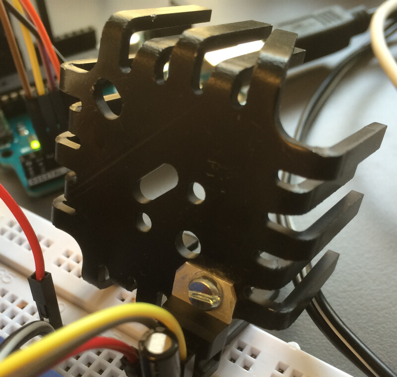
Currently I'm using a 9V power supply. With the heat shrink attached it's getting just a little bit warm but nothing more than just a little above body temperature. But then again, the heat shrink seems enormous in size compared to the little regulator (see picture)
The project is a part of an installation that is supposed to be powered on 24/7 for several months so would the heat be an issue for the components in the long run?
Just an observation of words:
heat shrink would make the component warmer,
while heat sink will help cool the component.
By viewing your image, I see you really meant heat sink.