which on the inside, contains some kind of a motor with 3 terminals, +, - and S (I've been told that this is essentially a voltmeter with a different scale):
I've already managed to create a circuit with a transistor to control the values via PWM, however, the system buzzes at any values other than 0 or 255. I'm pretty sure this is because of the PWM pulse turning on and off rapidly, and I've already read some about fast PWM, but I do have some questions:
Megas have multiple PWM pins (2 to 13). Would it be an issue using fast PWM on multiple pins? this should control 6 to 8 gauges, so I would need to do it for that amount of pins. I'm not sure if making PWM fast produces some kind of burnout or stress on the mega that could be harmful.
I'm not sure if you can control the frequency you can set the fast PWM to, code is a bit confusing for me. If so, how do I know what frequency should I use?
If I decide not to switch to fast PWM and leave the buzzing as is (it's not too loud), is this harmful for the motor? I've read that it can be annoying but has no real impact on the motor.
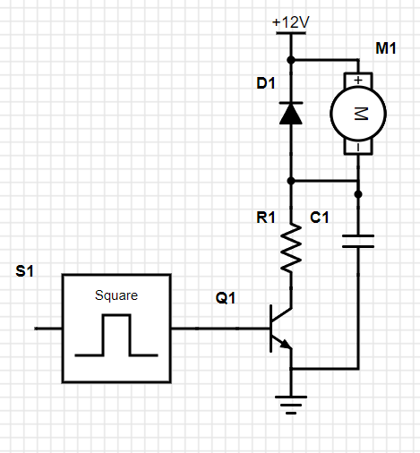
Thank you. So my circuit looks like this:
Where S1 is pin 2 (PWM) in the Arduino Mega.
I'm assuming the RC filter would be adding a resistor and a capacitor, I'm guessing at the collector of the transistor, right? Would the below be the correct diagram? and how do I calculate the R value? and the capacitor?
The time constant of a RC filter is R*C seconds. That's the time when a square wave input raises the output to about 2/3 of the input amplitude.
Placing the filter at the output end will result in low R and high C values. More practical is placing the filter before the transistor base, with handier component values but higher load on the transistor. In either case the transistor is working in the linear area and dissipating more heat than in switching (rectangular) mode.
M1 is a moving coil galvanommetr which responses to slowly varying DC excitation. Therefore, the PWM signal (with Mark/On and Spce/Off) must be somoothed using a LPF (low pass filter) before being asserted on the base of Q1 through a series resitor.
You may try using the following LPF with 1 kHz PWM signal.
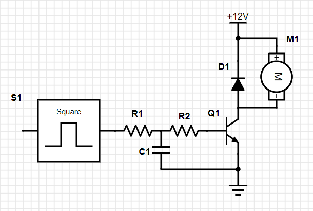
I'd split your 1k base resistor in two (2*470) and attach the capacitor between both to GND. You can start with a smaller cap and increase it until the effect is sufficient.
The splited resistor compensates the non-linear characteristic of the transistor BE diode.
I don't have that many components laying around. Do you think 2x510 resistors and a 10 microfarad cap will make it?
This would be the schematics, right?
Ok, I did try it, and unfortunately, looks like the cap is cancelling the PWM effect, so my code, that takes the needle up to 50% for 2 seconds, then to 100% for two more seconds and then to 0% for two more seconds, is only doing the 0 and the 100%.