FFT Library for Arduino Due, SAM3X

Thank you so much Magician however, if you could help me again, it would stop my head exploding!

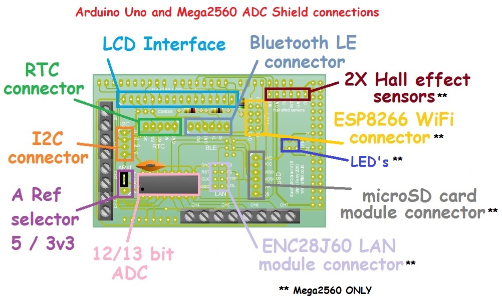
So, I have a project where I have designed an ADC shield which has a 12 bit ADC as well as connectors for Bluetooth, display and rtc. The idea is that the Arduino will sit there talking samples from up to 4 ADXL335 accelerometers, perform an fft, work out the overall acceleration and velocity readings which it will display on a 2004lcd, compare the readings to ISO standards for vibration and tell the user if these readings are healthy, in alert or alarm.

I have it working great on an Arduino MEGA2560 using an FFT library I found here ion the forum, but I'd like to change to a DUE and make use of the extra processing power and bigger fft sizes.

So, on the mega, the sampling routine is this

// Function fftsample(int chan, int b)
// reads samples from channel chan into global array fft_input
// b is step. use b=1 to get twf data for export
// use b=2 to get alternative twf data and zero's for fft
// ie real and imaginary data are interspersed

void fftsample(int chan, int samples, int b)
{
  unsigned long start_time;
  unsigned long next_time;
  double        twftot=0.0;
  
  int a;
  
  if(micros()>0xFFF0BDBF)   // micros is less than 1 second until rollover
    delay(1010);            // 1.01 second delay to take micros past rollover
    
  start_time = micros();
  next_time = micros()+391;
  for(a=0; a<samples; a+=b)
  {
    fft_input[a] = adc.analogRead(chan);    // put real data into even bins
    twftot+=fft_input[a];
    fft_input[a+1] = 0;                     // set odd bins to 0
    
    for(;;)
      if((long)micros()>next_time)
        break;

  next_time+=391;
  }
  twfavg=(int) (twftot/(samples/b));

}

This puts the real amn imaginary values into consecutive bins.

And the fft analysis part looks like this

        for(l =0; l<loops; l++)
        {
            vel[p]=0;       // holds the latest velocity reading for point P
            acc[p]=0;       // holds the latest acceleration reading for point p
            acum=0;         // cumulateve acceleration to work out overall
            vcum=0;         // cumulative velocity to work out overall

            fftsample(p,512,2);
            
            for(i=0; i<512; i+=2)
                fft_input[i]-=twfavg;   // subtracts average values ie dc offset
          
                       
            fft_window();       // window the data for better frequency response
            fft_reorder();      // reorder the data before doing the fft
            fft_run();          // process the data in the fft

            
            for(i=4; i<200; i+=2)   Skip lower bins and calculate overall values up to 1kHz
            {
                fft_input[i]=absolute(fft_input[i],fft_input[i+1]);
                acceleration=fft_input[i]*res*(1000/sensitivity);
                acum+=(acceleration*acceleration);
                    
                velocity=(acceleration*9806.65)/(twopi*10*i);
                vcum+=(velocity*velocity);
            }
            acc[p]=sqrt(acum/lineshape);
            vel[p]=sqrt(vcum/lineshape);

            
            if(!l)   // only print to screen on first run so no flicker
            {
                clearlcd();
                lcd.setCursor(0,0);
                lcd.print(point[p]);
                lcd.setCursor(0,1);
                lcd.print("  Vel          mms  ");
                lcd.setCursor(0,2);
                lcd.print("  Acc          g's  ");
                lcd.setCursor(0,3);
                lcd.print("  Status            ");
            }
   
            lcd.setCursor(9, 1);
            if(vel[p]<10)
                lcd.print(" ");
            lcd.print(vel[p],2);
            
            lcd.setCursor(9, 2);
            if(acc[p]<10)
                lcd.print(" ");
            lcd.print(acc[p],2);
            
            lcd.setCursor(10, 3);
            if(vel[p]<=3.5)
                lcd.print("Healthy");
            else if(vel[p]>3.5 && vel[p]<=7.1)
                lcd.print("Alert  ");
            else 
                lcd.print("ALARM  ");
                
            delay(750);
        }
        
    }

absolute is just sqrt((aa) + (bb)); ie the square route of the real squared plus the imaginary squared.

But when I try to get the same code to compile for the due, I get error messages .

So while surfing for a 'due' solution, I came across your code but even looking at the example, I'm not sure how to use it - I'm more likely to win at Wimbledon than I am to understand maths at that level! But like Marcus Willis, I do try!

So, from what I can see, there are the following functions used in your example.

radix.rev_bin( f_r, FFT_SIZE)
radix.fft_split_radix_real( f_r, LOG2_FFT)
radix.gain_Reset( f_r, LOG2_FFT -1)
radix.get_Magnit1( f_r, out1)
radix.get_Magnit2( f_r, out2)

So, lets say I call my modified fftsample() routine to put FFT_SIZE no. of samples into the variable f_r;
How do I use your functions to give me a comparable result to the functions I'm using now?

Can you please explain in 'Ball boy' terms what each function does so I and others like me, know which ones to use to get our desired results.

Thanking you so so much, Steve.

In your code:
fftsample(p,512,2);

In mine
sampling goes in background, based on timer 48 kHz, ADC - > DMA -> f_r[].

In your code:
for(i=0; i<512; i+=2)
fft_input*-=twfavg; // subtracts average values ie dc offset*

  • fft_window(); // window the data for better frequency response*
    In mine
  • for ( uint16_t i = 0, k = (NWAVE / FFT_SIZE); i < FFT_SIZE; i++ )*
  • { *
    uint16_t windw = Hamming[i * k];
    f_r = mult_shft12((inp[indx_a][indx_b++] - dc_offset), windw);
    * } *

In your code:
* fft_reorder(); // reorder the data before doing the fft*
* fft_run(); // process the data in the fft*
In mine
* radix.rev_bin( f_r, FFT_SIZE);
radix.fft_split_radix_real( f_r, LOG2_FFT);
radix.gain_Reset( f_r, LOG2_FFT -1);
Eather:
radix.get_Magnit1( f_r, out1);
OR
radix.get_Magnit2( f_r, out2);*

you need one magnitude calculation, here is from .cpp file:
> * There is two subfunctions for magnitude calculation, as you can see second one runs
> * more than 10x times faster, but it is less accurate, error in worst case scenario
> * may reach 5 %. Approximation based on
> *
_> * http://www.dspguru.com/dsp/tricks/magnitude-estimator_

Magician, Thank you for your help. I can't state enough how grateful I am. If you're ever in Cyprus, there's a few cans of Keo with your name on them!

So if I have this right, I edit my fftsample routine to collect FFT_SIZE samples at my required sampling rate of 2560hz ie (one per 391uSec) and put the data into the f_r array consecutively, not alternative bins for real amd imag. Also calculate the average value and store in variable dc_offset, not twfavg and in the loop I do the following;

fftsample(p,FFT_SIZE);
for ( uint16_t i = 0, k = (NWAVE / FFT_SIZE); i < FFT_SIZE; i++ ) 
{ 
uint16_t windw = Hamming[i * k];
f_r = mult_shft12((inp[indx_a][indx_b++] - dc_offset), windw);
} 

radix.rev_bin( f_r, FFT_SIZE);
radix.fft_split_radix_real( f_r, LOG2_FFT);
radix.gain_Reset( f_r, LOG2_FFT -1); 
radix.get_Magnit1( f_r, out1);

I assume radix.get_Magnit1 is similar to my absolute function to get the magnitudes from the real and imag parts of the result from the FFT. Where does the magnitude end up? still in the f_r array?

Cheers, Steve.

Obviously, array out1 - have you seen a library example, same name of the array goes for printing of the results.

CM_Guy:
Where does the magnitude end up? still in the f_r array?

No, it goes in out1 or out2 I have found.

So, I have tried to use your library and I seem to have failed somewhere.

I have an accelerometer attached to a motor which has some imbalance to ensure vibration. Using the following code;

#include    <MCP3208.h>
#include    <SplitRadixRealP.h>
#define     MIRROR         FFT_SIZE / 2
#define     INP_BUFF       FFT_SIZE 


MCP3208 adc(4);                             // initialise the SPI ADC with CS on pin 4 

double      res=3.3/4096.0;                 // 12bit resolution using 3.3V A.Ref
volatile    uint16_t   sptr     =   0 ;
volatile    int16_t   flag      =   0 ;
uint16_t    inp[2][INP_BUFF]    = { 0};     // DMA likes ping-pongs buffer
int         f_r[FFT_SIZE]       = { 0};
int         out1[MIRROR]        = { 0};     // Magnitudes
int         dc_offset; 


SplitRadixRealP     radix;

void setup() 
{
    
    adc.begin();
    Serial.begin(115200);
    
}


void loop()
{
    int a;
    uint16_t indx_a = 0;
    uint16_t indx_b = 0;

    Serial.println("Time Waveform");
    Serial.println();
    
        
    fftsample(0,FFT_SIZE);
    
    for(a=0; a<FFT_SIZE; a++)
        Serial.println((f_r[a]-dc_offset)*res,5);
        
    Serial.println();
    Serial.println("FFT ");
    Serial.println();
    
    for ( uint16_t i = 0, k = (NWAVE / FFT_SIZE); i < FFT_SIZE; i++ ) 
    {  
        uint16_t windw = Hamming[i * k];
        f_r[i] = mult_shft12((inp[indx_a][indx_b++] - dc_offset), windw);
    }
    radix.rev_bin( f_r, FFT_SIZE);
    radix.fft_split_radix_real( f_r, LOG2_FFT);
    radix.gain_Reset( f_r, LOG2_FFT -1); 
    radix.get_Magnit1( f_r, out1);

    for(a=0; a<FFT_SIZE/2; a++)
        Serial.println(out1[a]*res,5);
     
    while(1);
}

inline int mult_shft12( int a, int b)  
{
  return (( a  *  b )  >> 12);      
}


void fftsample(int chan, int samples)
{
  unsigned long start_time;
  unsigned long next_time;
  double        twftot=0.0;
  
  int a;
                            // sampling time for 2048 samples at 2560hz = 0.800768 seconds
  if(micros()>0xFFF0BDBF)   // micros is less than 1 second until rollover
    delay(1010);            // 1.01 second delay to take micros past rollover
    
  start_time = micros();
  next_time = micros()+391;
  for(a=0; a<samples; a++)
  {
    f_r[a] = adc.analogRead(chan);    // put real data into even bins
    twftot+=f_r[a];
    
    
    for(;;)
      if((long)micros()>next_time)
        break;

  next_time+=391;
  }
  dc_offset=(int) (twftot/(samples));

}

I print the output to the monitor so I can copy and paste into excel and I get a nice time waveform but a spectra with only 2 bins having values, the rest zeros.

Can you see anything obvious?

Oh, what about indx_a ? what should I be setting it to, I tried 0 because flag was either 1 or 2 in your example.

Steve.

What is the board, why you are using mcp3208?

Well, the reason I'm using MCP3208 is because I designed an ADC shield for the Mega2560 as 10 bits is not enough for my project. The board also has lots of other connections, RTC, Bluetooth and HD44780 LCD module being the most important ones to me.

The aim of the project is to attach several accelerometers to a machine - eg motor nde bearing, motor de bearing etc. The unit loops round checking the vibration levels by taking a sample, doing and fft and calculating overall levels in both velocity and acceleration. It then compares these levels to ISO standards and displays the levels and the machine condition on the lcd. If the condition is other than healthy, the user can download a twf via Bluetooth and email it to me for in depth analysis. Take a look at www.efftek-uk.com That's me, that's what I do!

So that's what the board is and why mcp3208. Now, I know that the due has 12 bit sampling, but the board was initially designed for the Mega which doesn't. See photos attached.

Steve.

The topic /thread name: "FFT Library for Arduino Due, SAM3X". It has noting to do with accelerometers or Mega2560.

Why you can't create your own new thread?

Magician:
The topic /thread name: "FFT Library for Arduino Due, SAM3X". It has noting to do with accelerometers or Mega2560.

Why you can't create your own new thread?

You asked me what board and why mcp3208, I explained.

However, I am now using that board on a Due, SAM3X and I want to use the FFT library which is in the thread name. The fact that I am using the board for the ADC rather than the ADC's on the Due should have bog all to do with it.

I am trying to use 'THE library' to do an FFT of 2048 samples on a 'Due, SAM3X' and I'm not getting a sensible result and as someone obviously knowledgeable in FFT's I am asking your advice. Surely THAT within the scope of THIS thread?

Your question isn't about the library. What you asking is for troubleshooting of your whole project, what I can't, as have no mcp3208, no wiring diagram, and no slightest intention to read your ridiculous code.
If there are doubts in fft procedure, than proof it, showing input data, output of the library, and why you think it's not correct.

Why the abuse? Why the need to call my code ridiculous? this attitude is unnecessary.

I am not asking you to troubleshoot my project.

You don't need mcp3208 - data is data if its from mcp3208, Due ADC or any other source. I know the sampling is OK. I am happy with that. I am asking why I'm not getting the expected output from your library, nothing more.

I am ONLY interested in how to use the library. I have isolated the relevant lines from my ridiculous code and would greatly value an answer.

Why does

uint16_t indx_a = 0;
** uint16_t indx_b = 0;
for ( uint16_t i = 0, k = (NWAVE / FFT_SIZE); i < FFT_SIZE; i++ )
_
{ *_
uint16_t windw = Hamming[i * k];
f_r = mult_shft12((inp[indx_a][indx_b++] - dc_offset), windw);
__ }__
radix.rev_bin( f_r, FFT_SIZE);
radix.fft_split_radix_real( f_r, LOG2_FFT);
radix.gain_Reset( f_r, LOG2_FFT -1);
radix.get_Magnit1( f_r, out1);[/b]*

not give expected results in out1?

not give expected results in out1?

Again speculation. Where is the data-proof?
Code is ridiculous because, why someone would put input data directly into f_r[] than do windowing function with inp[][]???

Er, maybe because not everyone is a brilliant as magician otherwise nobody would come on forum to ask for help because magician is so clever, he needs no help and magician only comes on forum to ridicule other peoples codes because obviously they are not brilliant like magician or they wouldn't be asking stupid questions and putting themselves up for ridicule. Perhaps.

As I said before, I have correct data values in the time waveform. But at the end of the FFT, I have data in first two bins on out1 and zeros in the rest. This is NOT a correct spectra from the time waveform therefore I know that the results are not as expected because although Im not a brilliant mathematician, Ive seen thousands of time waveforms and resultant spectras every year for past 25 years to be able to make that assessment.

Code provided:

  • THE SOFTWARE IS PROVIDED "AS IS", WITHOUT WARRANTY OF ANY KIND, EXPRESS
  • OR IMPLIED, INCLUDING BUT NOT LIMITED TO THE WARRANTIES OF
  • MERCHANTABILITY, FITNESS FOR A PARTICULAR PURPOSE AND NONINFRINGEMENT.

Please keep it civil, ladies.

I was so, so tempted not to keep it civil but I refuse to lower myself. I did, however, try to make a point. The purpose of this forum is that people who need advice can ask for it and they should never ever be belittled for doing so, no matter how daft the question.

They guy is obviously brilliant but disdains people who are not so clever and dare to ask for help. I am not the first to feel his contempt for those mere mortals who are beneath him and I wont be the last. Just check previous posts.

Whilst my code may not be as efficient as it could be, I like so many others on here am self taught, having never had the opportunity to go to university and study this sort of thing because 40 years ago, when I left school, this sort of thing hadn't been invented and apart from that, I had to get out into the world and earn a living and was down t'pit at 16.

To be told my code is ridiculous is extremely offensive. I just wish I could un-karma him. My offer of several Keo's certainly does not stand unless he wants me to shove them up his A*SE. Anyway, I wouldn't waste good Keo, he can have Leon instead!

upyors.jpg

The purpose of this forum is that people who need advice can ask for it and they should never ever be belittled for doing so, no matter how daft the question.

I agree about that,

and I also agree about the fact that Arduino libs in general do not always keep in real life what they promise to be capable of even if they are provided "as they are" by authors who do all that nitty pretty work non-obligatorily in their spare-time.

But I also agree that for trouble-shooting a common test set is required so that the developers can try to reproduce the faults or failures.

I know I will regret this in advance, and wholly expect the forthcoming flaming, however, I don't see the point creating another thread when my question pertains to the SplitRadixRealP library.

Here goes..........

I am not a novice, I am not a numbskull, but I know nothing about FFT. I have watched as many youtube video explanations as I can find and just ended up getting bogged down with Maths that is beyond me. When I did my electronics qualifications back in the mid 80's we were told FFT is a method of analyzing signals and you need a sample rate double the maximum frequency you wish to sample.

I understand the sample size will yield the same number of bins, I understand each bin to represent a single frequency.

From my limited knowledge and understanding so far, I can conclude that with a sample size of 2048, a SMP_RATE of 40000 will cover me to max frequency of 20kHz and give me frequency bins of approx 10Hz, what I am not sure of is how to determine the CLK_MAIN value.

If somebody with time and patience could explain in simple terms how to determine the relationship between these settings and correct me if any of my previous assumptions are incorrect, I would very much appreciate it.

Once I have all of this clear in my own mind, I could then do with knowing how to make use of the data collected.

Many thanks,

Regards,

Graham

EDIT: So my question was stupid and premature............... I will leave it here as a record, and explain my own question for the benefit of others just starting out in the world of FFT............

#define   SMP_RATE          40960UL 
#define   CLK_MAIN       84000000UL

The CLK_MAIN which I saw various values for so experimented myself........... should not be changed and is the clock speed of the DUE (84MHz), with a SMP_RATE of 40960 and sample size of 2048, the frequency step is 20Hz for example....

       79	140	60	6	2	0	0	0	0	0	0	0	0	0	0	0	
	0	0	0	0	0	0	0	0	0	0	0	0	0	0	0	0	
	0	0	0	0	0	0	0	0	0	0	0	0	0	0	0	0

The peak value of 140 in element 1 =20Hz

       -8	2	0	0	0	0	0	0	0	0	0	0	60	142	60	0	
	0	0	0	0	0	0	0	0	0	0	0	0	0	0	0	0	
	0	0	0	0	0	0	0	0	0	0	0	0	0	0	0	0

and here, the peak value in element 13 =260Hz

I hope this helps somebody.

Hi! I'm trying to achieve a similar goal as @DAN_X (or the same). I need to achieve maximum resolution with FFT as I can. I was following the comments and trying to make it but the wordpress from @Magician is broken :frowning:

Meantime I've also found out about the mystic "sum_dif_I" issue, by reading Magicians FFT block again and again - of course.
It's really a clever value overflow protection for bigger FFT array sizes. Now I've got it.
But under normal conditions, it is for the DUE user not so relevant until 32bit values leave plenty of bit space left.

I'm working the last two weeks to readapt the code but I couldn't find the mystic "sum_diff_I" Issue that DAN_X is talking about. Anyone has done a similar project? I'm using the code given from magician with Radix4 algorithm, but I cannot do it work.

I'm using 4096 points LUT tables

HammingWindowLUT.txt (30.9 KB)

sineLUT.txt (30.6 KB)

The link to the library is dead again. Does anyone know how to get it? I was specifically interested in settings up ADC + DMA for sampling audio signals. I feel somewhat bogged down by hard-to-understand details when reading SAM3X datasheets and appnotes without a working example to look at.

Alternatively, what are some tried-and-true FFT / DCT libraries for Arduino Due?