First time Etching PCB's

I'm going to venture into the world of home PCB etching. I have a kit, and I'll work out the specifics of that later, but for now, I'd like you experienced people to review my board design and comment if needed. I'm new to Eagle, and I'd like some feedback.

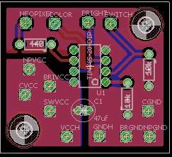
It's a simple 3d printed desklamp, using a 8x8 Neopixel board (Currenty having issues with the board with 64 LED's, but it runs fine on a breadboard with different strips of 16, It's a solder/wiring/bad board issue, I'll work it out). It will have a switch (Switch/SVCC) that will turn on all the LED's Bright white or a chosen color. A pot to control brightness (BRIGHT/BRIVCC/BRGND), and a pot to control which color (COLOR/CVCC/CGND). I'm using an ATTINY45 (Schematic says 85, but there wasn't a 45 listed, same chip though aside from memory), which will be mounted in a socket, not soldered directly to the board, so I can edit the code if necessary. Power will be from a 5v 3a wall wart with a power switch in the lamp.

I'd like comments on the board design. There's a ground pour on both sides to reduce the etching used. I'll be using 22g stranded. Mounted using 3mm Nylon screws into the lamp base.

I've read and watched a bunch of tutorials on the process, but if any of you guru's know of a good one, please share.

.sch and .brd are in the attached zip file.

Lampboard.png

lampschem.png

(Thank You Duane for the insert image trick)

#include <Adafruit_NeoPixel.h>

#define PIXELS 64 //Number of Pixels in Lamp
#define PIN 1    // NEOPIXEL Pin (AT 6)
#define SWPIN 3 // Switch Pin (AT 2)
#define POTPIN A2 // Brightness Pot Pin (AT 3)
#define COLPIN A1 // Color Pot Pin (AT 7)

Adafruit_NeoPixel strip = Adafruit_NeoPixel(PIXELS, PIN, NEO_GRB + NEO_KHZ800);

int newcol[3];
int col;

void setup()
{
  strip.begin();
  Show();
}

void loop()
{
  if (digitalRead(SWPIN)) // Bright white if switch is ON
  {
    for (int i = 0; i < PIXELS; i++)
    {
      strip.setPixelColor(i, 255, 255, 255);
    }

    while (digitalRead(SWPIN))
    {
      Show();
    }
  }

  col = map(analogRead(COLPIN), 0, 1023, 0, 764); //Set color with Pot
  ColorWheel(newcol, col);
  for (int i = 0; i < PIXELS; i++)
  {
    strip.setPixelColor(i, newcol[0], newcol[1], newcol[2]);
  }
  Show();
  
}

void ColorWheel(int* ptr, int wpos)
{
  if (wpos > 764 || wpos < 0) // Bright white if out of bounds
  {
    ptr[0] = 255;
    ptr[1] = 255;
    ptr[2] = 255;
  }
  else if (wpos <= 255)
  {
    ptr[0] = 255 - wpos;
    ptr[1] = wpos;
    ptr[2] = 0;
  }
  else if (wpos > 255 && wpos < 511)
  {
    ptr[0] = 0;
    ptr[1] = 510 - wpos;
    ptr[2] = wpos - 255;
  }
  else
  {
    ptr[0] = wpos - 510;
    ptr[1] = 0;
    ptr[2] = 765 - wpos;
  }

}

void Show()
{
  strip.setBrightness(map(analogRead(POTPIN), 0, 1023, 0, 255));
  strip.show();
}

NeoPixelLamp.zip (14.3 KB)

your angled traces are much too close to pads.

the trace should come out of the pad, turn, then run down the middle of the space between pads.

A test that I do is try to lay a trace between the pad and the actual trace. if there is not enough room, I adjust.

also for home etching, you do want to keep them further away. it gives you more options to make mistakes.

I like to put in extra holes, allow for an extra resistor or cap or some such.

lastly, on home etch, I would make the traces double wide. I use 20 mil

Hi Dave,

You should place an decoupling capacitor between your GND and VCC line coes to the device itself..
Another thing I should do is making your VCC connections more solid.
You could use a split plane on top or bottom for that.

Regards,
Luc

The lines are dangerously thin for home etching. Many of them will probably have breaks.

I always add an external 10K pullup resistor to the 'Reset' pin, to ensure that I don't get unintended resets.
Much of the time you can get away with the internal pullup, but I don't take the chance. A resistor is cheap. :slight_smile:
A capacitor to ground is also suggested for noisy environments, but I don't go that far.

The external pullup resistor is mentioned in section 2 of this application note:-
AVR042: AVR Hardware Design Considerations

Edit: As Dave mentioned, laying your tracks further from the pads is a good idea. Especially the track near pin 5. That's way too close for comfort. Also, whenever I have the space, I use 0.024" tracks, since thinner ones have no benefit but can end up with fine breaks as aarg says.
Edit2: I just saw your post, mart256. We're all in agreement regarding spacing and track width. :slight_smile:

For homeetching I use 20 mil, anything thiner is going to be difficult for a beginner. Check the clearance trace to pad, there is a pad kinda close to a trace, IVCC.

What home method are you using? Glossy paper?

Errr... I was going to use transparencies, and then photoresist.

As to tracing size, those are all auto-paths. The manual ones are much larger, I'll reroute the board with manual ones (It's not a complicated pathing).

10k resist on reset. Will do.

Decoupling cap. Will do.

Working on trying to figure out tracing size... Menus menus.... sigh... and clearances. Read a few books, watched a few videos on Eagle, but until I actually try it myself.... then I learn...

A good chunk of my issue is the number of items in the library list. I spend a good amount of time trying to find stuff. I just want a capacitor dangit!

Dont use auto if you want to learn, plus the board is small and has few traces.

Marmotjr:
A good chunk of my issue is the number of items in the library list. I spend a good amount of time trying to find stuff. I just want a capacitor dangit!

Download the Sparkfun libraries. I basically don't use anyone else's library. If the part is not in the Sparkfun library then I make my own library part.

I've been tempted too already morgan! Grrr. Even sparkfun's libraries are a bit confusing, but I'll remove most of the ones that don't make sense to me. Wait... none left. Should add a few that I can read a few of the words.

This really isn't a program to self teach. I appreciate the help guys!

I've learned more futzing around fixing mistakes this afternoon than I have the past month or so reading tutorials. So many thanks.

OK, here we go!

Not sure If I got the decoupling cap right. For as much as I love coding (And I'm not very good at it), electronics is some uncrackable mystery to me. Another version of this that I gave as a Xmas gift (it was set inside a custom frosted glass brick) was practically identical (aside from the obvious reset resistor and decoupling cap!), but had 900 lines of code. Yet I=V/C is still a mystery to me.

lamp1sch.png
lampbrd.png

NeoPixelLamp.zip (44.5 KB)

47uF isn't a decoupling cap. It's a power supply smoothing cap. A smaller capacitor like 1uF or 0.1uF is usually considered 'decoupling' as it damps out the megahertz-frequency stuff coming off digital chips. The inductance of a 47uF is too high to meaningfully trap that frequency.

Since you show a polarized cap, you're probably planning to use an electrolytic there. Electrolytic capacitors are tiny rolls of foil and chemicals. The rolled structure gives them the high impedance. A tantalum cap is also polarized but will have much less inductance for the same value. More dollars though.

I expect your circuit will work in the way that you have drawn it.

I've never worked with neopixels, so I don't know what connectors you usually use for them. I would set up the layout so that each neopixel string has a single connector on the board, instead of three wires going to different corners. Screw terminals might be appropriate connectors for this. Then try to get all the connectors onto one side of the board, so that it's easier to mount in an enclosure.

Hi,
The 47uF, you would be best to get one and measure it, or if ordering, look at data sheet for dimensions.
All manufacturers DO NOT make the same value electro cap in the same package.

Tom..... :slight_smile:
PS you can add extra vias to allow for physically bigger caps with bigger lead spacing.

PS you can add extra vias to allow for physically bigger caps with bigger lead spacing.

Good.

@Marmotjr, the 10K resistor on the reset pin should be a 'pullup', not a 'pulldown'. It needs to connect between the reset pin and Vcc, not between the reset pin and ground, or the chip will be held in perpetual reset. :frowning:
(Reset is active-low.)

Edit: I've never used "Eagle" before, and just installed it last night to look at your PCB layout. Looks like a steep learning curve.
I use an antique copy of "Protel Advanced PCB". It's far easier to use and produces great results, but isn't available any more. I've had it for 20+ years.
I'm not sure if 'Protel' even exist nowadays.

OldSteve:
Edit: I've never used "Eagle" before, and just installed it last night to look at your PCB layout. Looks like a steep learning curve.

very steep. many people advise that if you are getting into electronics for the long haul or professionally, then Eagle is a good choice.
alas, there are more than a few, much easier programs to learn.
but, be warned, that once you train your brain for the keystrokes and such, switching later gets harder.

Thanks again guys!

I'll switch out the cap for a smaller (1uf), non-polarized one (yes?). I did measure the cap, helped me figure out the nomenclature of the libraries a bit.

Thank you for the catch on the 10k!! That would be a horrible day.

Normally (on a bread board) I have all the Pixel wires off consecutive rows, but when I have transfered previous similar works to stripboard, I ended up using the buses. So all the red wires go over here, and the blacks over there, etc etc. I'll see what I can do about changing that up though, best practices and all. I do want these soldered to the board though, not through a screw terminals, as they can work loose, and I really don't plan on opening it up again once it's in use.

I've played with fitzring, but not that much. With all the negativity about it tossed around here, I figured I'd go for Eagle. While the learning curve is steep, I'm feeling I'm over the major hump of breaking into it.

Again thanks!

FYI
http://www.analog.com/media/en/training-seminars/tutorials/MT-101.pdf

dave-in-nj:
very steep. many people advise that if you are getting into electronics for the long haul or professionally, then Eagle is a good choice.
alas, there are more than a few, much easier programs to learn.
but, be warned, that once you train your brain for the keystrokes and such, switching later gets harder.

Ha, yeah, I know what you mean, Dave.
My brain is already trained for Advanced PCB, so I'll stick with it. I'm not sure if manufacturers still accept it's *.pcb files, but that doesn't matter now that I'm retired - I only need one-offs these days, and make them myself.

Back in it's day, (1995), 'Protel' was the best on the market. It still looks better than 'Eagle' when doing a layout, and has most of the features of newer software. (And a few that they don't.)
I'd show a screenshot, but it would be out of place here.

Ok, after seeing this: (Conway's Game of Life Nightlight by flimshaw - Thingiverse), I think I'll add a Game of Life Nightlight mode to the lamp!