Flashing and Bootloader Questions

Hi Everyone,

First, if I'm in the wrong place let me know.

I recently developed a custom PCB using the mega 2560 schematic. I've had to do a few modifications, but with the help of the AVR pocket programmer and the mega 2560 I've been able to burn the bootloaders. My PC is able to see the device as a mega 2560 and the IDE can see it as well. I've also been able to upload sketches via the AVR programmer. Now, I am unable to flash the atmega2560 via USB. The message below is what I get when attempting to upload via USB.

avrdude: stk500v2_ReceiveMessage(): timeout
avrdude: stk500v2_getsync(): timeout communicating with programmer

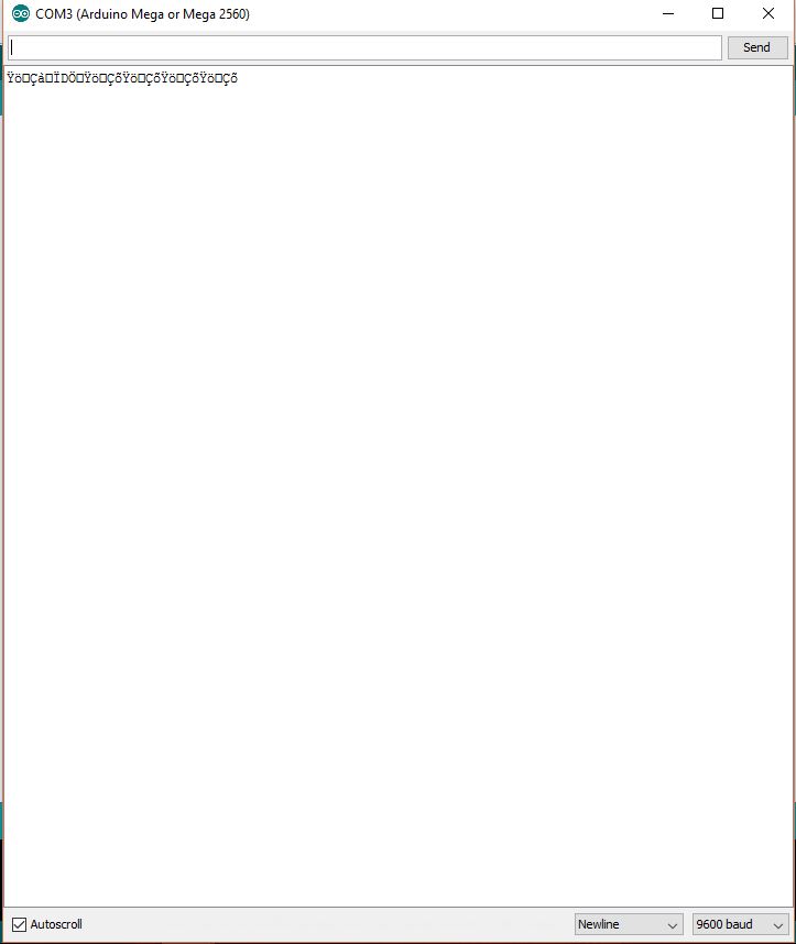
While having both ends of the bridge, to me, the bridge between the atmega2560 and atmega8u2 is not existant. I am using a atmega8u2 instead of a 16u2. This is by accident in my BOM. That being said, I was able to use the AVR command line interface to burn a 16u2 bootloader the the 8u2. After not being able to flash via the USB i decided to upload to the atmega2560 using the 'Upload using programmer' option with no error. I used an i2c scanner sketch to see if I might see anything from the serial monitor. This proved to yield different results as seen in the attached 'capture.jpg' serial monitor output. This jumbled output appeared regardless of baud setting.

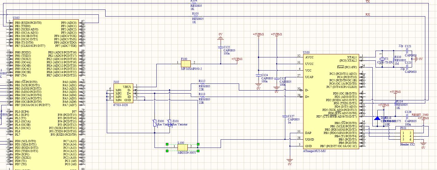
I thought I might be in error with the TX and RX lines. I have sat and compared my schematic (also attached) to the mega 2560 Rev 3 schematic and wasn't able to find anything noticable.

Could this be a problem due to the fact that I am using an 8u2 instead of a 16u2? Perhaps resistor values problems of R104 and R105? I should also note that I received the wrong components for the varistors (Z100, Z101) and currently have them unpopulated. Would this also cause problems?

I'd really appreciate some guidance or any information. Thanks for your time.

"Upload Using Programmer" = I've also been able to upload sketches via the AVR programmer.

That wipes out the bootloader and will prevent sketch uploading via the serial port, whether 8U2 or 16U2.

R104, R105 at 1K are fine.
Leaving off Varistors is also fine, they are just acting as surge suppressors.

So what I tried was burn the bootloader to the custom PCB atmega2560 using 'Arduino as ISP'. The completed without error. Once complete I removed the 'Arduino as ISP' mega2560 and connected the custom PCB to USB. I attempted to upload the i2c scanner only to receive the same message.

avrdude: stk500v2_ReceiveMessage(): timeout
avrdude: stk500v2_getsync(): timeout communicating with programmer

I feel like going in circles with this at this point.

Ok, here's my collection of random thoughts in no particular order:

You mentioned putting a bootloader on the ATmega8U2 but you did not mention the other software. You'll need to put the USB-to-serial program on it so it will act as a USB-to-serial converter. The USB-to-serial program hex file is a part of the Arduino IDE download, down in one of the subdirectories called firmwares.

I recommend breaking your project into parts, and test each part. For example, you can run the loop back test on the USB-to-serial chip, that is the test mentioned in one of the pinned posts at the top of the forum.
Check that the bootloader on the ATmega2560 flashes the pin 13 LED when you reset it, and then check if the flashing occurs when you open a serial connection via USB and the Serial Monitor. That would check that the auto-reset circuit works.

If you get all that working and still can't upload, check that you can upload to the ATmega2560 using an external FTDI or other USB-to-serial adapter. Connect it just like you were connecting an Arduino Mini: RX on the USB-to-serial adapter to TX on the ATmega2560, TX on the USB-to-serial adapter to RX on the ATmega2560, GND on the USB-to-serial adapter to GND on the ATmega2560, 5V on the USB-to-serial adapter to 5V on the ATmega2560, DTR on the USB-to-serial adapter to one leg of a 0.1uF cap, other leg of cap to Reset on the ATmega2560.

Check that you are using 16MHz crystals for both ATmega2560 and for ATmega8U2.

Connect a programmer and use avrdude to read and check the fuse settings for both processors to make sure they are right.
ATmega2560: lfuse 0xFF hfuse 0xD8 efuse 0xFD
ATmega8U2: lfuse 0xFF hfuse 0xD9 efuse 0xF4

Check your design that you have decoupling capacitors at each VCC and GND input of both ATmega2560 and ATmega8U2. Decoupling capacitors should be close to the MCU. Traces leading to the crystals should also be short.

In the Arduino IDE preferences check the show verbose output during upload checkmark. Post the output when it tries to upload. Also tell what settings you make on the Tools menu, what version of IDE you have, what operating system of the computer, show photos of your wiring and close up photos of your board. Post complete schematic of your board, the one you posted looked like it was chopped off.

Check your board completely for continuity and no shorts at each trace, check the solder joints they are well made. Try a different USB cable, different USB port, different computer if possible.

I recommend sticking with another Arduino as ISP, because pocket programmer will not properly address large memory of the ATmega2560 to put the bootloader in the right place.

Thanks Jmglambert. I'll go through these as much as I can. As a beginner PCB maker I have zero experience in making it through this portion of producing this piece of hardware. I have been successful in using the AVR programmer for burning the MEGA-dfu_and_usbserial_combined.hex to the 8u2. I've attached the CMD output. I am interested to know if they are talking to each other, but I did not include the LED from pin 13 in my design. Bad idea now that I'm here... I'll try hooking up my oscilloscope and see if I can see any pulsing. I've attached the Arduino part of my schematic for greater inspection.

For my next attempt I'm going to try and just program using the pocket programmer and the MainProgram.ino.with_bootloader.hex to the Atmega2560.

I dug up this thread thread, which has been going since 2011 about the similar problem.
https://forum.arduino.cc/index.php?topic=83079.0

I'll let you know how things go.