I’m starting to think the ‘flip-flop’ title was a red herring !
1 Like
i guess i'm not sure what you mean by flip flop. there are many types: s-r, j-k, d. i demonstrated an set-reset type
if you hit lock, it performs the lock sequence and switches to the lock state. hitting the lock button is ignored once in the lock state.
same for unlock.
i added prints. what does the serial monitor show?
2 Likes
And that is what is called for. The code seems to work fine.
Could it be as simple as buttons that are reading opposite to the sense of the lock and unlock signals?
Changing it to HIGH means pressed makes it loop contiousnly going locked and unlocked. It occurs to me that asserting both S and R in a set-reset flip flop is not recommened.
a7
2 Likes
The serial monitor shows 'locked' then 'unlocked', no matter if i send a signal into 'lock' or 'unlock' pins. Set/reset doesnt work for some reason. However it did with your first code, Led went on when locked, and only went off shen unlocked.
To answer other question - no, the moment i wrote in buttonstate == high, it began running off into constant loop of sequences snd stopping only when one of the signal inputs are triggered. So it is looking for LOW.
Perhaps a schematic of my circuit would help?
To use SR (Set Dominant) or RS (Reset Dominant), you must consider a dominant when choosing SR or RS to write your code to control a device.
SR (Set Dominant)
output = (output & !reset) | set;
RS (Reset Dominant)
output = (output | set) & !reset;
Please take a look at the below sketch for your reference,
#define lockPin 2
#define unlockPin 3
#define mirrorPin 9
#define ledPin 11

#define PULSE_DELAY 50
#define DEBOUNCE_PERIOD 10

typedef struct {
  bool input;
  bool state;
  unsigned long startDebounceTime;
  bool debounce(bool bounce);
} debounce_t;

bool debounce_t::debounce(bool bounce) {
  bool prevPounce = input;
  input = bounce;
  if (bounce & !prevPounce) {
    startDebounceTime = millis();
  }

  if (bounce != state) {
    if (millis() - startDebounceTime >= DEBOUNCE_PERIOD) {
      state = bounce;
    }
  }
  return state;
}

debounce_t lock;
debounce_t unlock;

bool locked;
bool prevLocked;

bool pulse;
unsigned long startPuleTime;

void setup() {
  Serial.begin(9600);
  pinMode(lockPin, INPUT_PULLUP);
  pinMode(unlockPin, INPUT_PULLUP);
  pinMode(mirrorPin, OUTPUT);
  pinMode(ledPin, OUTPUT);
}

void loop() {
  lock.debounce(!digitalRead(lockPin));
  unlock.debounce(!digitalRead(unlockPin));

  prevLocked = locked;

  // locked = (locked | lock.state) & !unlock.state; // Reset-Set (Reset Dominant)
  locked = (locked & !unlock.state) | lock.state; // Set-Reset (Set Dominant)
  digitalWrite(ledPin, locked);

  PulseCondition();
  digitalWrite(mirrorPin, pulse);
}

void PulseCondition() {
  if (locked != prevLocked) {
    startPuleTime = millis();
    pulse = true;
  }

  if (pulse) {
    if (millis() - startPuleTime >= PULSE_DELAY) {
      pulse = false;
    }
  }
}
the code i wrote expects a button to pull the pin LOW
what do you mean by "send a signal into lock" what is the state of the the pin when "lock"?
Here's the code from #19 with zero no changes in the simulator:

My beeper won't beep, you'd have to replace setting it HIGH with a call to *tone*(), and setting it LOW with a call to *noTone*(). I had that in there, it was fun I can hardly handle.
The other edit I had performed that I removed was to replace HIGH in the digitlRead() calls with a defined constant PRESST. Defined as LOW to accommodate @gcjr button choice.
// https://wokwi.com/projects/373213655222061057
// https://forum.arduino.cc/t/flipflop-type-of-code/1156858

// if a 'lock' signal is received:
//   mirror fold pin: go HIGH for 50ms, then go LOW.
//   hazard lights and horn pin: go high for 200ms, go low

// if 'unlock' signal is received:
//   mirror fold pin: go HIGH for 50ms, then go LOW.
//   hazard lights and horn pin: go high for 200ms, go low for 200ms,
//      go high for 200ms, go low.

const byte PinLock      = 2;
const byte PinUnlock    = 3;

const byte PinMirror    = 11;
const byte PinHorn      = 5;
const byte PinHazzard   = 8;

enum { Off = LOW, On = HIGH };
bool locked;

// -----------------------------------------------------------------------------
void
loop (void)
{
    if (! locked && LOW == digitalRead (PinLock)) {   // lock
        Serial.println ("lock");
        locked = true;

        digitalWrite (PinMirror,  On);
        digitalWrite (PinHorn,    On);
        digitalWrite (PinHazzard, On);

        delay (50);
        digitalWrite (PinMirror,  Off);

        delay (150);
        digitalWrite (PinHorn,    Off);
        digitalWrite (PinHazzard, Off);
    }

    if (locked && LOW == digitalRead (PinUnlock)) {   // un-lock
        Serial.println ("un-lock");
        locked = false;

        digitalWrite (PinMirror,  On);
        digitalWrite (PinHorn,    On);
        digitalWrite (PinHazzard, On);

        delay (50);
        digitalWrite (PinMirror,  Off);

        delay (150);
        digitalWrite (PinHorn,    Off);
        digitalWrite (PinHazzard, Off);

        delay (200);
        digitalWrite (PinHorn,    On);
        digitalWrite (PinHazzard, On);

        delay (200);
        digitalWrite (PinHorn,    Off);
        digitalWrite (PinHazzard, Off);
    }
}


void
setup (void)
{
    Serial.begin (9600);

    pinMode (PinLock,   INPUT_PULLUP);
    pinMode (PinUnlock, INPUT_PULLUP);

    pinMode (PinHorn,    OUTPUT);
    pinMode (PinHazzard, OUTPUT);
    pinMode (PinMirror,  OUTPUT);

    digitalWrite (PinHorn,    LOW);
    digitalWrite (PinHazzard, LOW);
    digitalWrite (PinMirror,  LOW);
}
So I don't know what's flying for @dainyzas. Yes, it is time for a schematic. Also, are we sure about the signals? You know, GIGO and all.
a7
rather than "us" debug the problem, why doesn't the OP take advantage of a learning opportunity and add prints to debug the problem?
add additional prints, and if necessary code to indicate when a "signal" occurs and from the understand why the "set/reset" doesn't do what is expected?
1 Like
Thank you all for your support. i Sat down for a bit more, and i edited your code a little with millis, and i got really close to what i actually need. The only thing is that it blinks/beeps only once for lock and unlock. the mirror pulse fiasco was solved.
this is the code.
#define lockPin 2
#define unlockPin 3
#define mirrorPin 8
#define ledPin 13
#define HornPin 5
#define HazzPin 11

#define PULSE_DELAY 50
#define DEBOUNCE_PERIOD 10

const long onDuration = 300;// OFF time for LED
const long offDuration = 200;// ON time for LED
int HazzPinState = LOW;// initial state of LED
int HornPinState = LOW;// initial state of LED


long rememberTime=0;// this is used by the code


typedef struct {
  bool input;
  bool state;
  unsigned long startDebounceTime;
  bool debounce(bool bounce);
} debounce_t;

bool debounce_t::debounce(bool bounce) {
  bool prevPounce = input;
  input = bounce;
  if (bounce & !prevPounce) {
    startDebounceTime = millis();
  }

  if (bounce != state) {
    if (millis() - startDebounceTime >= DEBOUNCE_PERIOD) {
      state = bounce;
    }
  }
  return state;
}

debounce_t lock;
debounce_t unlock;

bool locked;
bool prevLocked;

bool pulse;
unsigned long startPuleTime;

void setup() {
  Serial.begin(9600);
  pinMode(lockPin, INPUT_PULLUP);
  pinMode(unlockPin, INPUT_PULLUP);
  pinMode(mirrorPin, OUTPUT);
  pinMode(HazzPin, OUTPUT);
  pinMode(HornPin, OUTPUT);
  pinMode(ledPin, OUTPUT);
  digitalWrite(HazzPin,HazzPinState);// set initial state
  digitalWrite(HornPin,HornPinState);

}

void loop() {
  {
  lock.debounce(!digitalRead(lockPin));
  unlock.debounce(!digitalRead(unlockPin));

  prevLocked = locked;

  // locked = (locked | lock.state) & !unlock.state; // Reset-Set (Reset Domonant)
  locked = (locked & !unlock.state) | lock.state; // Set-Reset (Set Domonant)
  digitalWrite(ledPin, locked);

  PulseCondition();
  digitalWrite(mirrorPin, pulse);
  }
  {
  if( HornPinState == LOW )
 {
    if(digitalRead(lockPin)== LOW && ((millis()- rememberTime) >= onDuration)){
    HornPinState = HIGH;
    HazzPinState = HIGH;
    // change the state of LED
    rememberTime=millis();// remember Current millis() time
    }
 }
 else
 {
    if( (millis()- rememberTime) >= offDuration){
    HornPinState = LOW;
    HazzPinState = LOW;// change the state of LED
    rememberTime=millis();// remember Current millis() time
    }
 }
    digitalWrite(HornPin,HornPinState);
    digitalWrite(HazzPin,HazzPinState);
  }
}

void PulseCondition() {
  if (locked != prevLocked) {
    startPuleTime = millis();
    pulse = true;
  }

  if (pulse) {
    if (millis() - startPuleTime >= PULSE_DELAY) {
      pulse = false;
    }
  }


}
and here's the circuit.
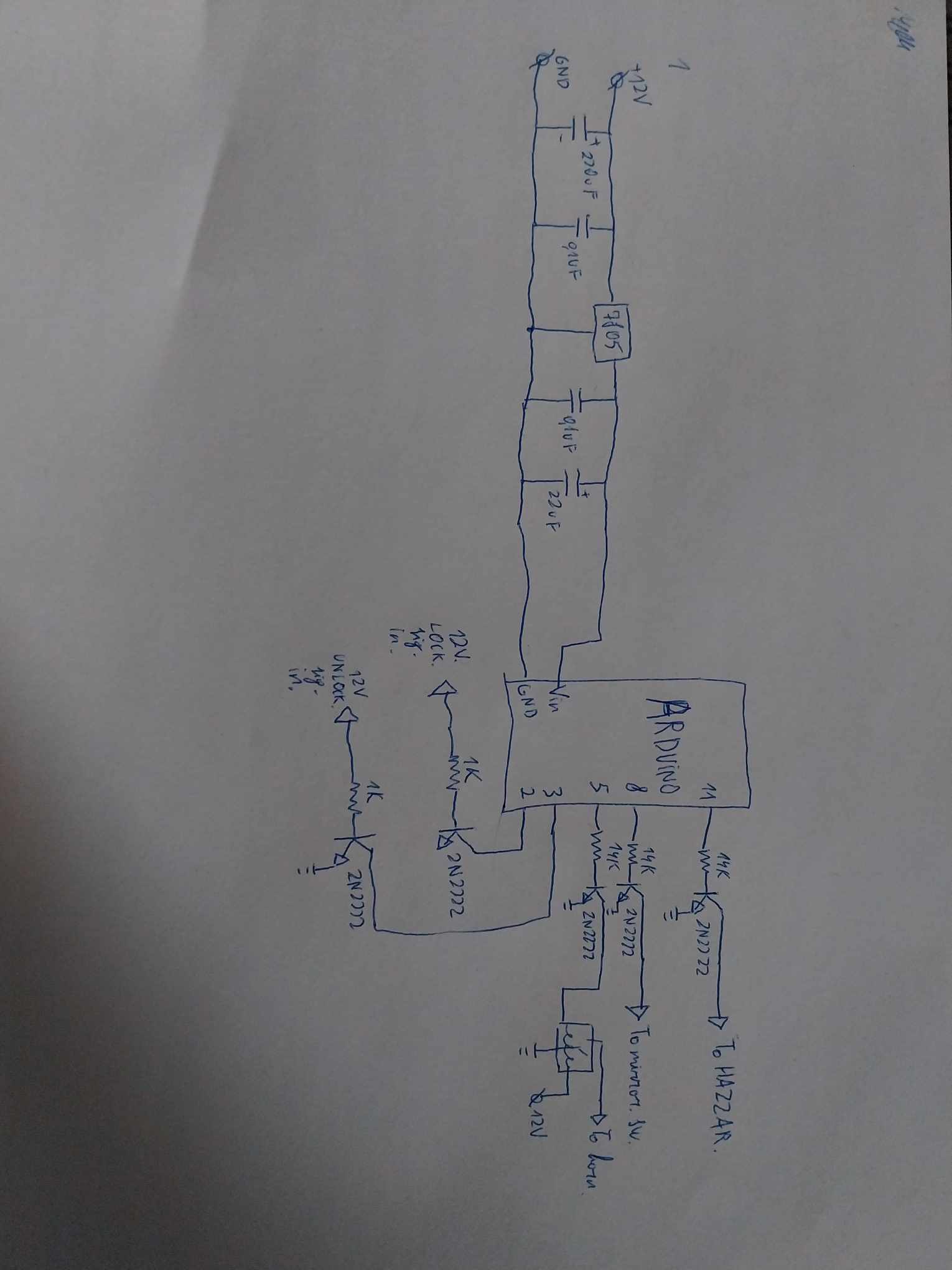
Hey, nice drawing!
I'm expecting my beach buddy to swing by, she who must not be kept waiting has texted and is rolling towards me.
I will look at your code L8R. Doing the double beep/blink is a bit trickier in the millis() world than just using delay().
Normally I avoid delay(), but with something this simple, and delays of fractions of a second, there is no particular shame in going the simple route.
Unless and until you actually have something to do in those milliseconds your previous version wasted, it may be that you don't really need to "improve" the process.
But I think it is worth running this new approach all the way to getting it to works as you desire.
Also, you may want need to place a diode across the relay.
flyback diode relay
Are those really 14K resistors? That seems a bit large.
a7
ah understandable, and thank you!
about the delay, i tried to actually use that instead and with millis, however, (i dont know if i do something wrong), the pulse no longer works, and flip-flop just doesnt work anymore.
about the diode - yes, im aware i need it, and il solder it in when il get my hands on one.
and yes, those are 14k resistors. im also sort of icky about them. perhaps a 4.7k would work better.
il patiently await your reply
don't know why you need to denouce the lock/unlock inputs if using a set/reset flip-flop. one the input is detected the flip-flop state prevents further action
so must have misunderstood your description of what you're trying to do
A kind of code that can do what you want is called a Finite State Machine.
At the simplest level with 2 process states OFF and ON (maybe 3rd for ERROR) each state runs one switch-case code allowing different actions depending on what's going on. The technique is extremely powerful when used in non-blocking code --- every state case needs to run a short step then return to execute the next command in void loop() without delay. A 16MHz Arduino can run state machines in loop() tens of times per ms when every one takes a short step only with 50,000 of those in every second... all of the the processes in void loop run smoothly together. It was a forum thing like switch debouncing before I got here in 2011.
State machine cases can change the state value. But the state value could be bits set by input pin states and maybe stored flags, a value results and that's the case that runs. It is Very General coding tool you really want!
Arduino Uno IO pins are connected in the chip as 8 bit digital ports with port registers that you can read and set all 8 at the same time. You may b-need to bit-logic-operate to only affect some pins (to avoid messing with pins used for something else) but..
Up to six pins on an Uno (when using Serial) can be read in one cycle and turned into a number in one more with two bits that can be added. The state bits make a number, the number case runs without need of ifs, ands, ors and parens .... the state bits include all that.
Did you ever make switches and lights logic gates? The flip-flop was the most advanced i saw. I did not try making a register of those.
most likely i did. im not very experienced with coding, so im learning as i go. and i have a feeling i delved into codes that arent for beginners.
i just read up a bit on the FSM. It seems to be much more simple than the last code i posted in this thread. At the same time, it seems quite complex. I think i should try to mock something up using FSM
a flip-flop is a 2 state FSM
part of coding is knowing how to test and how to debug
if coding is 1 unit of time (man-month), designing which describes how to do it cab be ~4 units and requirements which describes "what" needs to be done, completely, correctly and unambiguously, can be ~9 units.
perhaps it is still unclear what you want to do.
i thought you wanted some action to occur when a signal is recognized and not to repeat that action until after a different signal is recognized. you described 2 signal/actions
step one to automation is non-blocking code, here is a good intro.
With non-blocking and state machines you have 98% of automation and the other 2% if that needs interrupts.
1 Like
I think we just misunderstand each other, haha.
Il try to explain again.
If 'lock' signal is received:
Mirror pin (send a single 50ms signal) and ignore repeat 'lock' signal inputs
Hazzard and horn pins go on for 200ms
Hazzard and horn pins go off
(Each time 'lock' signal is received)
If 'unlock' signal is received:
Mirror pin (send a single 50ms signal) and ignore repeat 'unlock' signal inputs
Hazzard and horn pins go on for 200ms
Hazzard and horn pins go off for 100ms
Hazzard and horn pins go on for 200ms
Hazzard and horn pins go off
(Each time 'unlock' signal is received)
Thank you! Il check it out when i have a bit more free time!
so you only want to generate the mirrorPin pulse once using the flip-flop logic.
the other actions get repeated for each lock or unLock signal