If you could try my last code and help me improve it, I would really appreciate it. Thank you!
loop() is using micros() to generate the signals
however,, you are also printing information in loop() which could upset the timing
try
// ESP32 three phase square wave variable duty cycle using micros()

#define phase1 16  // signal output pins
#define phase2 18
#define phase3 17

#define PERIOD 1000                           // period 1KHz is 10000
#define DUTY_CYCLE 80                         // percentage
#define PULSE_WIDTH PERIOD* DUTY_CYCLE / 100  // resultant pulse width

unsigned long timerPeriod = 0;  // timer counter using micros()
unsigned long timerPhase1 = 0;
unsigned long timerPhase2 = 0;
unsigned long timerPhase3 = 0;

void setup() {
  Serial.begin(115200);
  delay(2000);
  Serial.println("\n\nESP32 timer three phase square wave with duty Cycle");
  pinMode(phase1, OUTPUT);  // enable phase outputs
  pinMode(phase2, OUTPUT);
  pinMode(phase3, OUTPUT);
  digitalWrite(phase3, 1);
  timerPeriod = micros();     // initialize period counter
}

// display interrupt coun ter every seconds
void loop() {
  static byte state = 0;  // determines which phase to generate
  if ((micros() - timerPeriod) > PERIOD / 3) {
    timerPeriod = micros();
    switch (state) {
      case 0:
        digitalWrite(phase1, HIGH);  // set phase output HIGH
        timerPhase1 = micros();      // cstart timer
        break;
      case 1:
        digitalWrite(phase2, HIGH);
        timerPhase2 = micros();  // cstart timer
        break;
      case 2:
        digitalWrite(phase3, HIGH);
        timerPhase3 = micros();  // cstart timer
        break;
    }
    if (++state >= 3) state = 0;  // reset state ?
  }
  if (timerPhase1 > 0 && (micros() - timerPhase1) > PULSE_WIDTH) {
    timerPhase1 = 0;
    digitalWrite(phase1, LOW);  // set phase output LOW
  }
  if (timerPhase2 > 0 && (micros() - timerPhase2) > PULSE_WIDTH) {
    timerPhase2 = 0;
    digitalWrite(phase2, LOW);  // set phase output LOW
  }
  if (timerPhase3 > 0 && (micros() - timerPhase3) > PULSE_WIDTH) {
    timerPhase3 = 0;
    digitalWrite(phase3, LOW);  // set phase output LOW
  }
}
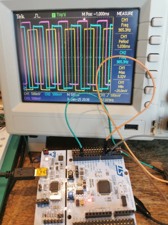
on ESP32 gives similar results to post 19
does not use any specific ESP32 functions so should run on the Zero
1KHz 50% duty cycle

The problem with the code you posted is that it uses delayMicroseconds(), which is "blocking code", which wastes the Arduino's processing time and preventing other "tasks" from running.
How can I prevent the blocking code on my Arduino and ensure I get my three signals with varying frequencies? Could you test Horace's code to see if it runs on your board?
ran the code of post 22 (using micros() to generate the signals) on a ST NEUCLEO-L073RZ board
only changes were to the pin definitions to suit the STM32
#define phase1 5  // signal output pins
#define phase2 6
#define phase3 7
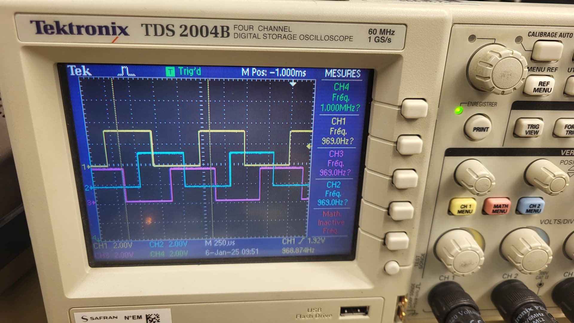
code ran OK, e.g. 1KHz three phase square wave 50% duty cycle
Don't use delayMicroseconds(). Your code uses micros() to time when each of the PWM pins should go HIGH. Use a similar technique to time when those pins should go LOW.
using the STM32 hardware timer to generate three phase square wave
// STM32 Nucleo board three phase square wave

#define phase1 5  // signal output pins
#define phase2 6
#define phase3 7

#include "STM32TimerInterrupt.h"

// To be included only in main(), .ino with setup() to avoid `Multiple Definitions` Linker Error
#include "STM32_ISR_Timer.h"

#define HW_TIMER_INTERVAL_US 10L

// Init STM32 timer TIM1
STM32Timer ITimer(TIM2);

// Init STM32_ISR_Timer
STM32_ISR_Timer ISR_Timer;

volatile int counter = 0;  // interrupt counter
void TimerHandler() {
  static byte state = 0;  // determines which phase to invert
  switch (state) {
    case 0: digitalWrite(phase1, !digitalRead(phase1)); break;  // invert phase 1
    case 1: digitalWrite(phase3, !digitalRead(phase3)); break;  // invert phase 3
    case 2: digitalWrite(phase2, !digitalRead(phase2)); break;  // invert phase 2
    case 3: digitalWrite(phase1, !digitalRead(phase1)); break;  // invert phase 1
    case 4: digitalWrite(phase3, !digitalRead(phase3)); break;  // invert phase 3
    case 5: digitalWrite(phase2, !digitalRead(phase2)); break;  // invert phase 2
  }
  if (++state >= 6) state = 0;  // reset state ?
  counter++;
}

void setup() {
  Serial.begin(115200);
  while (!Serial)
    ;
  delay(2000);
  Serial.println("STM32 Nucleo board three phase square wave");
  pinMode(phase1, OUTPUT);
  pinMode(phase2, OUTPUT);
  pinMode(phase3, OUTPUT);
  digitalWrite(phase3, 1);
  // Interval in microsecs
  if (ITimer.attachInterruptInterval(HW_TIMER_INTERVAL_US * 10, TimerHandler)) {
    Serial.print(F("Starting ITimer OK"));
  } else
    Serial.println(F("Can't set ITimer. Select another freq. or interval"));
}

// display interrupt counter every seconds
void loop() {
  static unsigned long timert = millis();
  if (millis() - timert >= 1000) {
    Serial.println(counter);
    counter = 0;
    timert = millis();
  }
}

serial monitor output
STM32 Nucleo board three phase square wave
Starting ITimer OK9998
9999
10000
9999
9999
9999
9999
9999
9999
9999
9999
9999
EDIT: tested on a STM32 Black Pill STM32F401 F411 works OK with pin settings
#define phase1 PB5  // signal output pins
#define phase2 PB6
#define phase3 PB7
for some reason I thought the target microcontroller was a STM32 device but I realize it is a SAMD21
ran the code of post 22 (using micros() to generate the signals) on a MKRFOX (which uses a Arm® Cortex®-M0 32-bit SAMD21 processor) board
only changes were to the pin definitions to suit the MKRFOX
// MKRFOX SAMD21 processor three phase square wave variable duty cycle using micros()

#define phase1 1  // signal output pins
#define phase2 2
#define phase3 3
code ran OK, e.g. 1KHz three phase square wave 50% duty cycle

Thank you! I'm going to try the code from post 22 on Monday on my Arduino Zero to see if it works. I'll change the pins to make it compatible. Do you think I can use a potentiometer to change the frequency and still maintain a good phase shift? Can you confirm if, on your oscilloscope, you see phase shifts of 0°, 120°, and 240° at 1 kHz?
just try changing the value of PERIOD (1000 is 1KHz) - you will need to make PERIOD and PULSE_WIDTH variables
phase shifts should be OK
e.g. changed PERIOD to 2000 uSec

Are you simulating a motor or a motor controller? It seems like the latter as you want to generate the signals. There are processors that have special timers that are suitable for generating signals for BLDC motor commutation. That would allowing offloading much of the task from software to hardware. Check out Teensy 4.0 for example.
I want to be able to go from 5 Hz to a maximum of 1 kHz using the potentiometer. I need to calculate my period and variable frequency, as shown in my code in post #20.
I want to simulate the motor
the following code runs on a MKRFOX SAMD21 and enbles changing the period and duty cycle by entering characters on Serial Monitor keyboard
// MKRFOX SAMD21 processor three phase square wave variable duty cycle using micros()

#define phase1 1  // signal output pins
#define phase2 2
#define phase3 3

unsigned long period = 1000;                            // period 1KHz is 10000
unsigned long duty_cycle = 50;                          // percentage
unsigned long pulse_width = period * duty_cycle / 100;  // resultant pulse width

unsigned long timerPeriod = 0;  // timer counter using micros()
unsigned long timerPhase1 = 0;
unsigned long timerPhase2 = 0;
unsigned long timerPhase3 = 0;

void setup() {
  Serial.begin(115200);
  delay(2000);
  Serial.println("\n\nMKRFOX SAMD21 three phase square wave with duty Cycle using micros()");
  pinMode(phase1, OUTPUT);  // enable phase outputs
  pinMode(phase2, OUTPUT);
  pinMode(phase3, OUTPUT);
  digitalWrite(phase3, 1);
  timerPeriod = micros();  // initialize period counter
  Serial.println("period increment > (* by 10) decrement < (/ by 10)");
  Serial.println(" duty cycle enter 1 (for 10%) to 9 (for 90%)\n");
}

// display interrupt coun ter every seconds
void loop() {
  static unsigned long int unit = 1000;
  // check if updated period or duty cycle entered
  while (Serial.available()) {  // if characters entered read them
    char ch = Serial.read();
    if (!isprint(ch)) continue;
    if (ch == '>') {
      period += unit;
      if (period / unit >= 10) unit *= 10;
    }
    // < decrement value by 1 unit  - minimum is 1 ?
    if (ch == '<' && period != 1) {
      if (period == unit) unit = unit / 10;
      period -= unit;
    }
    // * increment value by 10 ?
    if (ch == '*') {
      period = unit = unit * 10;
    }
    // / decrement value by 10 - minimum is 1
    if (ch == '/' && period != 1) {
      if (period == unit) unit = unit / 10;
      period = unit;
    }
    if ((ch >= '1') && (ch <= '9')) duty_cycle = (ch - '0') * 10;  // set duty cycle
    pulse_width = period * duty_cycle / 100;
    Serial.print("period = ");
    Serial.print(period);
    Serial.print(" frequency = ");
    Serial.print(1000000.0 / (period));
    Serial.print(" dutyCycle ");
    Serial.println(duty_cycle);
  }
  // output pulses HIGH using micros() as timer
  static byte state = 0;  // determines which phase to generate
  if ((micros() - timerPeriod) > period / 3) {
    timerPeriod = micros();
    switch (state) {
      case 0:
        digitalWrite(phase1, HIGH);  // set phase output HIGH
        timerPhase1 = micros();      // set timer for pulse width
        break;
      case 1:
        digitalWrite(phase2, HIGH);
        timerPhase2 = micros();
        break;
      case 2:
        digitalWrite(phase3, HIGH);
        timerPhase3 = micros();
        break;
    }
    if (++state >= 3) state = 0;  // 3 phases - reset state ?
  }
  // if pulses HIGH and pulse_width exceeded go LOW
  if (timerPhase1 > 0 && (micros() - timerPhase1) > pulse_width) {
    timerPhase1 = 0;
    digitalWrite(phase1, LOW);  // set phase output LOW
  }
  if (timerPhase2 > 0 && (micros() - timerPhase2) > pulse_width) {
    timerPhase2 = 0;
    digitalWrite(phase2, LOW);  // set phase output LOW
  }
  if (timerPhase3 > 0 && (micros() - timerPhase3) > pulse_width) {
    timerPhase3 = 0;
    digitalWrite(phase3, LOW);  // set phase output LOW
  }
}
serial monitor output
MKRFOX SAMD21 three phase square wave with duty Cycle using micros()
period increment > (* by 10) decrement < (/ by 10)
 duty cycle enter 1 (for 10%) to 9 (for 90%)

period = 10000 frequency = 100.00 dutyCycle 50
period = 100000 frequency = 10.00 dutyCycle 50
period = 200000 frequency = 5.00 dutyCycle 50
5Hz output

be carful - the pulse timing is done in loop()
if you upset the loop timing by carrying out complex operations in loop() the pulse output will be effected
as @gfvalvo pointed out it is preferable to use hardware generators if available, e.g. on the ESP32 I have used the RMT to generate pulse sequences - the SAMD21 probably has a similar interafce
I tried your code today, and it works perfectly! It's exactly what I was looking for thank you. However, I noticed a slight desynchronization in the phase shift, but it's not very important. I would like to know if it's possible to replace the multiplication (*) and division (/) functions with a potentiometer. When I build the project, the board will be inside a box, and we won’t be able to use a computer later.
yes - remove the Serial input code and replace with potentiometer code
I replaced the serial input and then connected the potentiometer, but the duty cycle changes and doesn't stay at 50%
#define phase1 1  // signal output pins
#define phase2 2
#define phase3 3

unsigned long period = 1000;  // initial period in microseconds
unsigned long duty_cycle = 50;  // percentage
unsigned long pulse_width = period * duty_cycle / 100;  // resultant pulse width
unsigned long timerPeriod = 0;  // timer counter using micros()
unsigned long timerPhase1 = 0;
unsigned long timerPhase2 = 0;
unsigned long timerPhase3 = 0;

int frequency = 1000;  // initial frequency in Hz

void setup() {
  Serial.begin(115200);
  delay(2000);
  Serial.println("\n\nMKRFOX SAMD21 three phase square wave with duty Cycle using micros()");
  pinMode(phase1, OUTPUT);
  pinMode(phase2, OUTPUT);
  pinMode(phase3, OUTPUT);
  digitalWrite(phase3, 1);
  timerPeriod = micros();
}

void loop() {
  // Lire la valeur du potentiomètre pour la fréquence
  int potValueFreq = analogRead(A0);
  frequency = map(potValueFreq, 0, 1023, 5, 1000);  // Plage de 10 Hz à 1000 Hz
  period = 1000000 / frequency;  // Calculer la période en microsecondes

  pulse_width = period * duty_cycle / 100;  // Recalculer la largeur d'impulsion

  // Afficher les valeurs (pour debug)
  Serial.print("Frequency = ");
  Serial.print(frequency);
  Serial.print(" Hz, Period = ");
  Serial.print(period);
  Serial.print(" us, Duty Cycle = ");
  Serial.println(duty_cycle);

  // Générer les signaux carrés
  static byte state = 0;  // détermine quelle phase générer
  if ((micros() - timerPeriod) > period / 3) {
    timerPeriod = micros();
    switch (state) {
      case 0:
        digitalWrite(phase1, HIGH);
        timerPhase1 = micros();
        break;
      case 1:
        digitalWrite(phase2, HIGH);
        timerPhase2 = micros();
        break;
      case 2:
        digitalWrite(phase3, HIGH);
        timerPhase3 = micros();
        break;
    }
    if (++state >= 3) state = 0;
  }

  // Si impulsion HIGH et largeur d'impulsion dépassée, passer à LOW
  if (timerPhase1 > 0 && (micros() - timerPhase1) > pulse_width) {
    timerPhase1 = 0;
    digitalWrite(phase1, LOW);
  }
  if (timerPhase2 > 0 && (micros() - timerPhase2) > pulse_width) {
    timerPhase2 = 0;
    digitalWrite(phase2, LOW);
  }
  if (timerPhase3 > 0 && (micros() - timerPhase3) > pulse_width) {
    timerPhase3 = 0;
    digitalWrite(phase3, LOW);
  }
}
with potentiometer

and your code :
The duty cycle changes, and I don't understand why.
analogRead(A0) takes so long it is upsetting the timing of the loop
try reading the pot once a second
// display interrupt coun ter every seconds
void loop() {
  // output pulses HIGH using micros() as timer
  static byte state = 0;  // determines which phase to generate
  if ((micros() - timerPeriod) > period / 3) {
    timerPeriod = micros();
    switch (state) {
      case 0:
        digitalWrite(phase1, HIGH);  // set phase output HIGH
        timerPhase1 = micros();      // set timer for pulse width
        break;
      case 1:
        digitalWrite(phase2, HIGH);
        timerPhase2 = micros();
        break;
      case 2:
        digitalWrite(phase3, HIGH);
        timerPhase3 = micros();
        break;
    }
    if (++state >= 3) state = 0;  // 3 phases - reset state ?
  }
  // if pulses HIGH and pulse_width exceeded go LOW
  if (timerPhase1 > 0 && (micros() - timerPhase1) > pulse_width) {
    timerPhase1 = 0;
    digitalWrite(phase1, LOW);  // set phase output LOW
  }
  if (timerPhase2 > 0 && (micros() - timerPhase2) > pulse_width) {
    timerPhase2 = 0;
    digitalWrite(phase2, LOW);  // set phase output LOW
  }
  if (timerPhase3 > 0 && (micros() - timerPhase3) > pulse_width) {
    timerPhase3 = 0;
    digitalWrite(phase3, LOW);  // set phase output LOW
  }
  static unsigned long timer = millis();
  if (millis() - timer > 2000) {
    timer = millis();
    int potValueFreq = analogRead(A0);
    unsigned long int frequency = map(potValueFreq, 0, 1023, 5, 1000);  // Plage de 10 Hz à 1000 Hz
    period = 1000000 / frequency;                                       // Calculer la période en microsecond
    pulse_width = period * duty_cycle / 100;                            // Recalculer la largeur d'impulsion
    Serial.println(potValueFreq);
    Serial.print("period = ");
    Serial.print(period);
    Serial.print(" frequency = ");
    Serial.print(frequency);  //1000000.0 / (period));
    Serial.print(" dutyCycle ");
    Serial.println(duty_cycle);
    Serial.print(" pulse_width ");
    Serial.println(pulse_width);
  }
}
I would tend to use a rotary-encoder
This code works perfectly with some delay. Sometimes, I get the impression that the duty cycle isn't correct, but it still works. Thank you, I appreciate it!
could be due to once a second reading pot and display data
see if this version using timers is better
// MKRFOX SAMD21 processor three phase square wave using timer  plus duty cycle

// from https://github.com/khoih-prog/SAMD_TimerInterrupt


// These define's must be placed at the beginning before #include "SAMDTimerInterrupt.h"
// _TIMERINTERRUPT_LOGLEVEL_ from 0 to 4
// Don't define _TIMERINTERRUPT_LOGLEVEL_ > 0. Only for special ISR debugging only. Can hang the system.
// Don't define TIMER_INTERRUPT_DEBUG > 2. Only for special ISR debugging only. Can hang the system.
#define TIMER_INTERRUPT_DEBUG 0
#define _TIMERINTERRUPT_LOGLEVEL_ 0

// Select only one to be true for SAMD21. Must must be placed at the beginning before #include "SAMDTimerInterrupt.h"
#define USING_TIMER_TC3 true  // Only TC3 can be used for SAMD51
#define USING_TIMER_TC4 true  // Not to use with Servo library
#define USING_TIMER_TC5 true
#define USING_TIMER_TCC true
#define USING_TIMER_TCC1 false
#define USING_TIMER_TCC2 false  // Don't use this, can crash on some boards

#include "SAMDTimerInterrupt.h"

#define phase1 1  // signal output pins
#define phase2 2
#define phase3 3

unsigned long int period = 334;                             // timer interval in uSec
unsigned long duty_cycle = 50;                              // percentage
unsigned long pulse_width = period * 3 * duty_cycle / 100;  // * 50 / 100;

// Init selected SAMD timer
SAMDTimer ITimer(TIMER_TCC);
SAMDTimer ITimerPhase1(TIMER_TC4);
SAMDTimer ITimerPhase2(TIMER_TC5);
SAMDTimer ITimerPhase3(TIMER_TC3);

// timer interrupt routine
volatile int counter;
void TimerPeriod() {
  static byte state = 0;  // determines which phase to invert
  switch (state) {
    case 0:
      digitalWrite(phase1, HIGH);
      // ITimerPhase1.attachInterruptInterval(pulse_width, TimerPhase1);
      //ITimerPhase1.enableTimer();
      ITimerPhase1.reattachInterrupt();
      ITimerPhase1.restartTimer();
      break;  // invert phase 1
    case 1:
      digitalWrite(phase2, HIGH);
      ITimerPhase2.reattachInterrupt();
      ITimerPhase2.restartTimer();
      //   ITimerPhase1.attachInterruptInterval(pulse_width, TimerPhase2);
      break;  // invert phase 2
    case 2:
      digitalWrite(phase3, HIGH);
      ITimerPhase3.reattachInterrupt();
      ITimerPhase3.restartTimer();
      //   ITimerPhase1.attachInterruptInterval(pulse_width, TimerPhase3);
      break;  // invert phase 3
  }
  if (++state >= 3) state = 0;  // reset state ?
  counter++;
}

void TimerPhase1() {
  digitalWrite(phase1, LOW);
  ITimerPhase1.stopTimer();
  ITimerPhase1.detachInterrupt();
}

void TimerPhase2() {
  digitalWrite(phase2, LOW);
  ITimerPhase2.stopTimer();
  ITimerPhase2.detachInterrupt();
}

void TimerPhase3() {
  digitalWrite(phase3, LOW);
  ITimerPhase3.stopTimer();
  ITimerPhase3.detachInterrupt();
}

void setup() {
  Serial.begin(115200);
  while (!Serial && millis() < 5000)
    ;
  delay(100);
  Serial.print(F("\nMKRFOX SAMD21 processor three phase square wave using timer"));
  Serial.println(BOARD_NAME);
  Serial.println(SAMD_TIMER_INTERRUPT_VERSION);
  Serial.print(F("CPU Frequency = "));
  Serial.print(F_CPU / 1000000);
  Serial.println(F(" MHz"));
  pinMode(phase1, OUTPUT);
  pinMode(phase2, OUTPUT);
  pinMode(phase3, OUTPUT);
  digitalWrite(phase3, 1);
  Serial.println("rotate potentiometer to change period/frequency");
  Serial.println(" duty cycle enter 1 (for 10%) to 9 (for 90%)\n");
  setup_timers();
}

// setup times
void setup_timers() {
  // Interval in microseconds
  if (ITimer.attachInterruptInterval(period, TimerPeriod)) {
  } else
    Serial.println(F("Can't set ITimer. Select another freq. or timer"));
  if (ITimerPhase1.attachInterruptInterval(pulse_width, TimerPhase1)) {
  } else
    Serial.println(F("Can't set ITimerPhase1. Select another freq. or timer"));
  ITimerPhase1.stopTimer();
  ITimerPhase1.detachInterrupt();
  if (ITimerPhase2.attachInterruptInterval(pulse_width, TimerPhase2)) {
  } else
    Serial.println(F("Can't set ITimerPhase2. Select another freq. or timer"));
  ITimerPhase2.stopTimer();
  ITimerPhase2.detachInterrupt();
  if (ITimerPhase3.attachInterruptInterval(pulse_width, TimerPhase3)) {
  } else
    Serial.println(F("Can't set ITimerPhase3. Select another freq. or timer"));
  ITimerPhase3.stopTimer();
  ITimerPhase3.detachInterrupt();
}

void loop() {
  // if new duty cycle entered read it
  while (Serial.available()) {  // if characters entered read them
    char ch = Serial.read();
    if (!isprint(ch)) continue;
    if ((ch >= '1') && (ch <= '9')) duty_cycle = (ch - '0') * 10;  // set duty cycle
  }
  static unsigned long timer = 0;//millis();
  // read potentiometer every second  to get frequency
  if (millis() - timer > 1000) {
    timer = millis();
    int potValueFreq = analogRead(A1);
    unsigned long int frequency = map(potValueFreq, 0, 1023, 5, 1000);  // Plage de 10 Hz à 1000 Hz
    period = 1000000 / frequency;                                           // Calculer la période en microsecond
    pulse_width = period * duty_cycle / 100;                            // Recalculer la largeur d'impulsion
    Serial.println(potValueFreq);
    Serial.print("period = ");
    Serial.print(period);
    Serial.print(" frequency = ");
    Serial.print(frequency);  //1000000.0 / (period));
    Serial.print(" dutyCycle ");
    Serial.print(duty_cycle);
    Serial.print(" pulse_width ");
    Serial.println(pulse_width);
    period = period/3;  // timing for 3 phases
    setup_timers();
  }
}
rotate pot to change frequency enter 1 to 9 to change duty cycle