Hey everyone! Thanks to the great help I received on this forum, I obtained all of the components I needed for my project and I now have a working prototype on my breadboard.
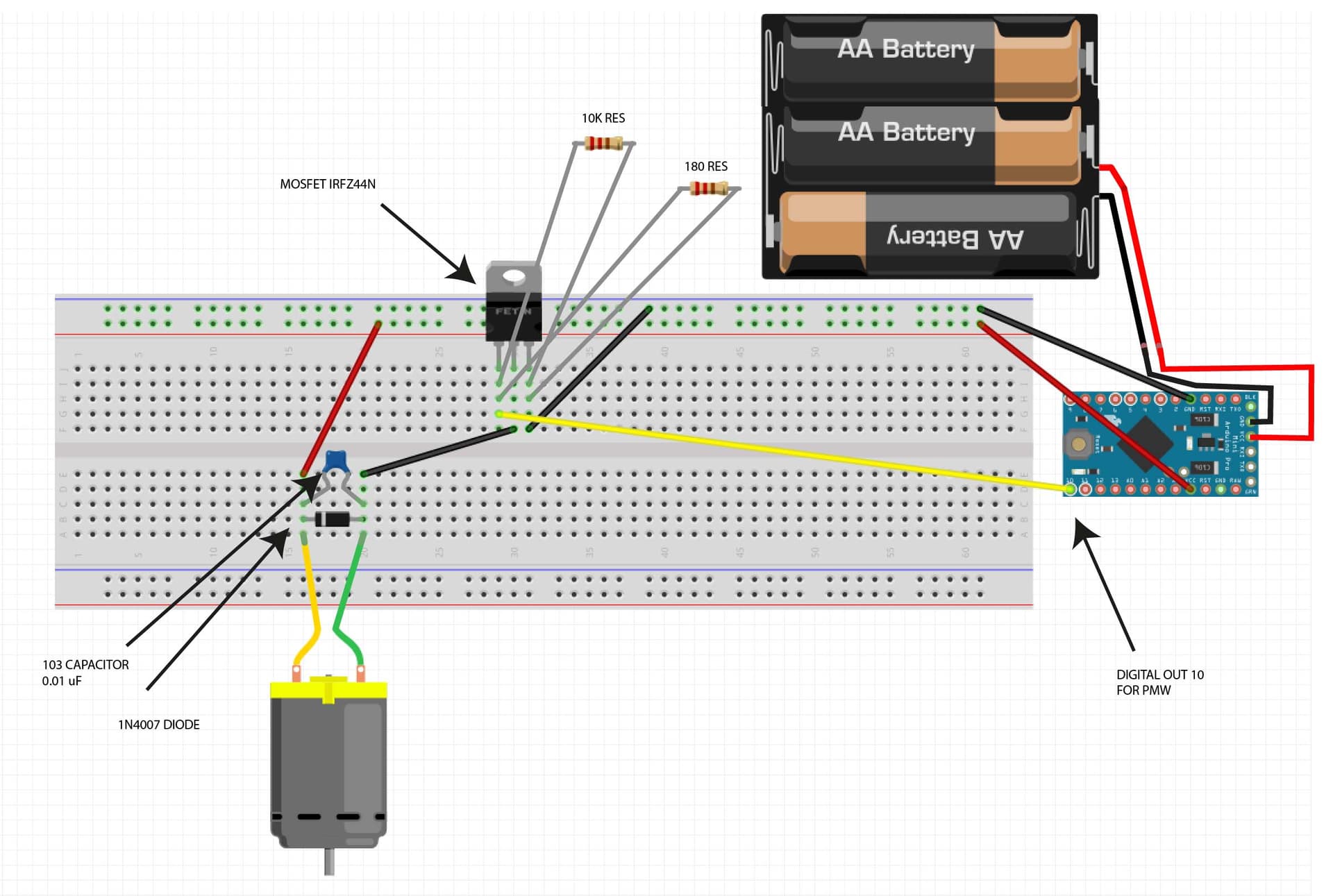
I'm developping a very simple circuit that controls a DC motor, slowing it down to about 33RPM using an Arduino Pro Mini and a MOSFET motor driver.
Although my breadboard prototypes work, I have to admit I feel like I wired it wrong. I watched tutorials and based myself off of others breadboards that I found online, but the whole thing still seems... fishy.
I would like for someone to quickly review my wiring and tell me if I'm missing anything. Sorry for the terrible Fritzing diagram, I struggled to do something clean on the software.
And this is the current state of my breadboard. I'm not yet using 3 AA battery to power the Arduino, but instead using the USB to SATA adapter to give 3.3V to the Arduino VCC pin, then using the VCC & GND pin to power my breadboard. My motor is spinning correctly, and the code I have is working successfully. (Nevermind the weird battery compartment. I couldn't find a 3 AA battery on Fritzing so I photoshop it instead.)
Good job on the photo shop. With your skill I would consider learning CAD (Computer Aided Design) software for electronics such as KiCad, it is free as are many other packages. Schematics is the written language of electronics.
Never run power through pin boards they will not survive. Also running motor power through your Arduino is a big No No.
I am not sure about your MOSFET, you did a great job with the pull down resistor but without knowing the MOSFET parameters I cannot determine if it is adequate for the job. You need to look at the Vgs curve to check if it will conduct the current at the supplied gate voltage. Many designs on the web show the pulldown resistor at the gate of the MOSFET with a another resistor to the port pin, this is a bad design as the resistors form a voltage divider lowering the Vgs voltage. You did it correctly as the pull down resistor will keep the mosfet off during reset etc until the processor gets control.
Whenever possible get an avalanche rated MOSFET, that eliminates the flyback diode requirement. If you use one anyway it will not hurt anything but the MOSFET will conduct before the diode. The diode needs to be sized for the motor current. Many use the 1A devices and at larger loads they will eventually fry.
You can connect the motor at the battery instead of the Arduino.
Thanks for all your answers, there are some things I don't quite understand.
If I can't run motor current through a breadboard, how am I supposed to prototype the circuit?
The IRFZ44 MOSFET was recommended to me by several members here on the forum. It's working with my Arduino 3.3V but the pinout is weird, I made it work by playing around. What's a better MOSFET for my use case?
Running motor power through my Arduino is a big nono, alright, but then, how am I suppose to both power the Arduino and the motor? Off of the same batteries but with a separate circuit?
The Mini is not plugged into the Breadboard as it is designed to.
Solder up the MOSFET (the replacement one), the diode, cap and some screw connectors to a small piece of stripboard. For tracks on the stripboard that will carry the high motor current, put a thick layer of solder (enough to cover the unused holes).
There are many members on this forum and many are beginners and should not be giving advice to other beginners.
You can attempt to isolate the arduino from the voltage drop when the motor is turned on with a diode and a large cap.
I need 12 of those. And I was thinking of simply adding a Arduino Mini footprint to the board with all the correct wiring, and just soldering the Mini on top of the PCB with headers.