Help needed for Arduino guitar tuner

Hello everyone, I'm am currently trying to make a acoustic guitar tuner as a project and I am running into some problems. Currently using a Arduino Uno, swapping between two sound sensors to check if there is any difference and a lCD display with I2C which i will remove for simplicity for now. These are my sound sensors:first one is and second one.

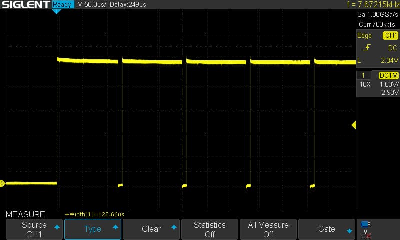
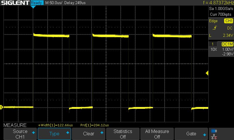
My problem is that when i struck any of the string the frequencies are either way higher than the ones that should be either because of the mic quality or environmental noises (or both).

My Arduino code: Arduino G-tuner - Pastebin.com

#include <arduinoFFT.h>

#define SAMPLES 128
#define SAMPLING_FREQUENCY 22050 // Adjust this based on your microphone's characteristics

arduinoFFT FFT = arduinoFFT();

unsigned int samplingPeriod;
unsigned long microSeconds;

double vReal[SAMPLES];
double vImag[SAMPLES];

// Define the frequency range for the guitar strings
const double MIN_FREQUENCY = 40.0;  // Adjust based on your guitar's lowest string
const double MAX_FREQUENCY = 1000.0; // Adjust based on the highest string

void setup() {
  Serial.begin(115200);
  samplingPeriod = round(1000000.0 / SAMPLING_FREQUENCY);
}

void loop() {
  // Read microphone input
  for (int i = 0; i < SAMPLES; i++) {
    microSeconds = micros();
    vReal[i] = analogRead(0) - 512.0; // Center the signal around 0
    vImag[i] = 0;

    while (micros() < (microSeconds + samplingPeriod)) {
      // Wait for the desired sampling period
    }
  }

  // Perform FFT
  FFT.Windowing(vReal, SAMPLES, FFT_WIN_TYP_HAMMING, FFT_FORWARD);
  FFT.Compute(vReal, vImag, SAMPLES, FFT_FORWARD);
  FFT.ComplexToMagnitude(vReal, vImag, SAMPLES);

  // Find peak frequency (dominant note)
  double peak = FFT.MajorPeak(vReal, SAMPLES, SAMPLING_FREQUENCY);

  // Check if the detected peak frequency is within the desired range
  if (peak >= MIN_FREQUENCY && peak <= MAX_FREQUENCY) {
    // Print detected peak frequency to Serial Monitor
    Serial.print("Detected Guitar String Frequency: ");
    Serial.print(peak);
    Serial.println(" Hz");
  }

  //delay(1000); // Add a delay of 1 second (adjust as needed)
}

I'm also thinking of adding a pick(vibration sensor) if that may help to cancel any environmental noises.

Any help towards the code or new components is welcome.
My apologies for the code.

Welcome. First, let's make this a usable post. Post the code in a new message, inside code tags. The instructions were shown to you when you signed up.

Also, a question: Where do you position the sensor when you tune?

Another: You mentioned swapping sensors but didn't explain why.

Another: You didn't show how you have them connected.

Thank you for your fast respond. I've tried to correct some mistakes in my post.
The two sensors I swap just because i want to see if there will be any difference in the detected frequency.

From what I've seen on the forum, most people making guitar tuners fail. :frowning: I've also read that something called "autocorrelation" works better than FFT or FHT.

I'm not sure how commercial guitar tuners are made but they must know some "tricks" because they are cheap. :wink:

This is tricky because there are harmonics & overtones... It's the harmonicas & overtones that make a guitar sound different from a trumpet when they are both playing the same note.

Those additional (and mostly higher) frequencies really do exist but you're trying to read/measure the fundamental frequency. Sometimes the harmonics are stronger than a fundamental. ...The lowest note on an acoustic piano ai an "A" at 27.5Hz but most of what you hear is harmonics. (I don't know if the fundamental is weaker or if it just sounds weaker because our ears are less sensitive to lower frequencies.)

I saw an electric guitar signal on an oscilloscope once and the signal was "complex" when first plucked and as it decayed it started to look like a clean sine wave (fewer harmonics & overtones).

You can record it Audacity and then look at the waveform and you can plot the spectrum to see the harmonics & overtones. I don't know if that will help but it will help you to understand the complexity.

1 Like

...and the results were?

You didn't answer, "Where do you position the sensor when you tune?". Looking at your photo, are you just picking up the sound in the room?

The photo does not really allow me to see how the wires are connected. Please post a wiring diagram, use pen and paper and label all connections.

Another problem will be the inaccurate CPU clock on the Uno...

First question: have you connected the AO pin (Analog Out) of the sensor to an Arduino analog input A0, and not the DO (Digital Out), right? I hope so.

Next, I can't find a schematics for that sensors (and I don't know cyrillic) so are you sure they give you about 5V peak to peak, and offset centered around 2.5V?

Third, if the answer to previous questions are both "yes", have you tested the sensors and FFT library with a frequency detection sample code, to make sure it works and recognises the frequencies?

Please read HERE for an useful Instructable sample code and wiring (even if it doesn't use your exact sensor and the project is for an electric (or electrified) guitar, the concepts are the same and that article contains some useful information).

Hope it helps.

I didn't think that an Arduino Uno could do analogRead(0), and take samples at 22050 per second.

So i added two lines to your sampling routine, so that I could use an oscilloscope to measure how long the analogRead(0) takes.

PORTB = B00010000; takes pin D12 high (in 62.5ns - faster than using digitalWrite(12,HIGH);).
PORTB = B00000000; takes pin D12 low again.
(Plus added pinMode(12, OUTPUT); to setup).

 // Read microphone input
  for (int i = 0; i < SAMPLES; i++) {
    microSeconds = micros();
    PORTB = B00010000;                  // D12 high
    vReal[i] = analogRead(0) - 512.0;   // Center the signal around 0
    vImag[i] = 0;
    PORTB = B00000000;                  // D12 low
    while (micros() < (microSeconds + samplingPeriod)) {
      // Wait for the desired sampling period
    }
  }

And here are the results:

It is taking 123μs to do the analogRead.

By setting the sampling rate to 22050, you are expecting the analogRead(0) to take less than 45μs, which it can't do.

I changed the sampling rate to 5000, which the Uno can do.
The results were a lot closer to being correct.

Using a 440Hz sinewave signal from a function generator, I got the following results:

I think that the error is now due to the fact that the timing is incorrect as the line

 for (int i = 0; i < SAMPLES; i++) {

is outside the timing loop and takes a few extra microseconds.

For Sampling frequency of 5000, the period should be 200μs, but i measure it as 204.12μs
.

This topic was automatically closed 180 days after the last reply. New replies are no longer allowed.