Hello, I have a setup of an Arduino Mega paired with magnet reed switches, relays, and an audio controller (Fright Props BooTunes) to control the audio and lighting for an escape room. At certain points an actor in the room uses a magnetic ring to inconspicuously trigger the magnet reed switches, telling the Arduino to set off certain relays to change lighting/audio, playing out specific scenes. It works pretty reliably most of the time, but occasionally scenes will be triggered randomly by what I'm assuming is EMI. I know some of if was being caused by activity in the two other rooms we have at our location (magnet locks releasing or things being powered on, etc.), but I'm pretty sure we've mitigated those factors already. Now we get occasional triggers when nothing obvious is happening. Possibly static from the actor when near the electronics?
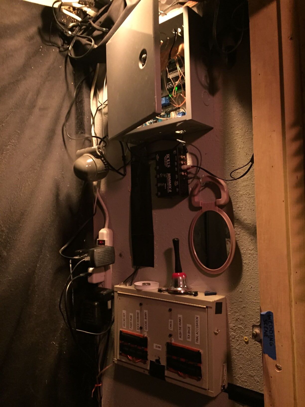
I'll give a brief rundown of the setup along with some pics, any advice is very much appreciated! Essentially there are 3 magnet reed switches embedded in the walls about 10-15ft away from the Arduino. Each one triggers a different set of relays for specific amounts of time. I'm using a few 5v relays and two of the relay power outlets (Controllable Four Outlet Power Relay Module version 2 [(Power Switch Tail Alternative)] : ID 2935 : $39.95 : Adafruit Industries, Unique & fun DIY electronics and kits). All the main electronics are inside a metal box with a copper tape ground strip connected to the box itself. All the input/output wires have ferrite beads around them where they come out of the box. I read somewhere that putting capacitors between the input wires and ground can help too, any thoughts/tips on that?
Also let me know if posting my code would be helpful, can't access it right now but can post it later if requested. I don't have any sort of debounce in triggers. It's very simple - mag reeds are N.O. between an INPUT_PULLUP pin and ground. When an input pin is pulled LOW, the code calls a loop that pushes certain relays high and changes a corresponding variable (i.e. y = 10, now y = 11). In the void loop, there are 'if' statements waiting for the variable change (y = 11) and a certain amount of time (in millis) to pass to end the given scene (i.e. pull the relay pins back to LOW so the audio and lighting go back to normal)
The only suggestion I have is try to categorize everything into one of two categories:
A: Stable- always works as expected
B: Unstable- unpredictable
If everything falls into category B then trouble-shooting it is going to be challenging if not impossible.
It's easy to throw around the word "EMI" but if you're working with devices that require proximity to a magnet then EMI is not to be expected. "EMI" is to non-electronics people as the "Boogey-Man" is to children. If you're not dealing with radio frequency and you are not bundling high current cables with low voltage analog or digital cables , then I don't see how you can bring up the issue of EMI.
Electro-Magnetic Interference is not something that is going to trigger a relay.
I can't rule out software but if you are not an electronic technician by profession (you get paid to work on electronics on a daily basis) , then anything could be possible. There's a thousand things that could be wrong with your setup if you are not a trained professional.
So what is it ?
Is this just a hobby project or some side interest or are you a working technician ?
Unfortunately, this doesn't look like something that can be debugged using text posts.
We're going to need a complete schematic if you expect to get anywhere with this.
What you have told is so far is of no help in troubleshooting it, except the part about the magnets.
That's helpful. Magnets are very predicable. How you are detecting them may be at the center of the
problem.
an actor in the room uses a magnetic ring to inconspicuously trigger the magnet reed switches
magnetic reed switches are used for security systems which gives you an idea of their reliability.
You're going to need to narrow it down somehow.
If I only had one question to ask right now, it would be :
No opto isolated relay modules, and five relays powered from Arduino's 5volt pin.
Seems like asking for trouble.
What is the supply voltage on the DC socket.
Mains switching contacts for complex (inductive) loads might need snubbering (R/C or varistor).
Low voltage inductive switching might need kickback diodes.
Leo..
Power for the Mega is 12v 1A. I am completely self taught when it comes to electronics so I've missed out on a lot of things that might seem common sense to those who have gone through a formal education. So yes, raschemmel, I am a working technician, doing this for my job, but I am very much an amateur in many regards, hence why I am asking for help, raschemmel, you sound like a lot of fun at parties. I used the term EMI, because as far as I know, that's what I'm dealing with. There are 30+ magnetic locks in our unit constantly going off as the rooms are played, which releases an electro-magnetic voltage spike when they are released (so I've read, but I'm open to non-asshole correction). We have kickback diodes on all our mag locks to try to reduce the voltage spikes, and since putting those in we haven't been getting false triggers from them any more.
Wawa, would you recommend putting kickback diodes across the relay contacts that are switching lights? From what I can tell, it is the Arduino that is mistakenly calling one of the scene loops. I say this because it's never individual relays that go off, it is always specific sets of relays that go off for specific amounts of time (as indicated in the code). Also I haven't looked into opto isolated relays, so I'll check that out. Is that something I can build in to my existing circuit?
What else can I provide that would be helpful for troubleshooting? I can draw up a rough schematic
The question was WHAT is powering the mega (not the voltage) , but WHAT DEVICE ?
WHAT IS IT ?
(ie, battery, ac/dc power supply etc)
If you're running that off ac power then I am not surprised it is unstable.
Simple suggestion . Run the Mega off a battery. (NOT an AC powered supply)
I could also recommend a shit ton of electrolytic filter caps and 0.1 uF decoupling caps.
Scattered around your circuit , preferably close to the Mega.
raschemmel, you sound like a lot of fun at parties.
Did you come here to party or to fix your circuit ? (And yes, I was partying before you were born. I saw Janis Joplin and Jimi Hendrix live so that should give you a clue)
You could try adding snubbers across the lock solenoid coils.
Are the false triggers synchronous with lock triggers ?
raschemmel:
The question was WHAT is powering the mega (not the voltage) , but WHAT DEVICE ?
WHAT IS IT ?
IT'S A DC ADAPTER RASCHEMMEL. SOMETIMES DIFFERENT PEOPLE HAVE DIFFERENT WAYS OF COLLOQUIALLY REFERRING TO THINGS SO I AM SO SORRY I MISINTERPRETED YOUR QUESTION.
The problem with battery power in our case is that it needs to be running all day (11am-midnight) four days/week. Why does running it off an AC power strip mean "unsurprisingly unstable"? Legitimate question, I'm not familiar with the instability of AC.
I could also recommend a shit ton of electrolytic filter caps and 0.1 uF decoupling caps.
Scattered around your circuit , preferably close to the Mega.
Where do you recommend putting the caps? Across the input wires and ground? like this -
(not my image)
Did you come here to party or to fix your circuit.
Mostly to fix my circuit, but I'm always ready to party if you'll be there to harangue me
Are the false triggers synchronous with lock triggers ?
No, unfortunately. They were when I was first putting the system together, but I installed diodes across all the mag locks and that seemed to stop that particular flavor of false trigger.
12volt is waaay to high for a Mega that has to power five 80mA relays.
You should not power more than one relay with that voltage. That 12-5= 7volt (6.3volt actually) is has to drop, with a several hundred mA load, generates a lot of heat in the 5volt regulator. It could randomly shut down (if you're lucky) when getting too hot.
For starters, power the Mega with a 5volt cellphone charger, connected to the USB socket.
Common practice to use opto isolated 4-relay or 8-relay boards with removable JD-VCC jumpers, that you can power with a separate 5volt (cellphone) supply.
Not sure if you should use these relay boards for mains related stuff in a public place.
Using opto isolation could add another layer of protection though.
Opto isolated boards need other hookup (no shared ground) and different code (setup and inverted logic).
Post a link to the relay boards before ordering.
Leo..
Are you saying there is no time to switch the power over to another battery because you're
running constantly or because the logistics of using a battery is inconvenient.
Do you want to SOLVE your problem , or just run around in circles ?
As a professional Electronics Engineering Technician , I'm telling you that if you
try using a battery and it eliminates the false triggers then that CONFIRMS the interference is not so much EMI as garbage on the AC line. Sometimes extreme problems require extreme measures.
I'm not going to guarantee that the false triggers will go away, but until you try it , you won't know
if they would.
If that's too much trouble for you then you can take the long road which is start adding snubbers across the electronic locks (probably not relevant because you said the false triggers were not synchronous with lock energizing), and 470uF to 1000uF electrolytics on the Mega 5V line and everywhere you have a logic signal driving something.
First you need to perform the experiment to see if the false triggers go away when you power the Mega off a battery. Until you have done that, you're nowhere. If that experiment is a success then, you can switch from a primary battery to a backup battery using an AC contactor energized with a 12V relay. Then you can charge your primary battery while running off the backup battery. Use a toggle switch for the 12V relay that drives the contactor.
Where do you recommend putting the caps? Across the input wires and ground? like this -
NO. It looks like you drew snubbers connected to the signal lines.
I don't understand what that is all about .
The RC Snubbers go across electromechanical devices (like lock solenoids, or across relay contacts.)
If you put filter caps on all the 5V lines everywhere and 0.1uF decoupling caps near all the logic, you reduce the amount of interference on the signal lines. Since you have not identified which lines are
being falsely triggered, it's really hard for us to be specific.
BTW, Wawa's suggestion of opto isolators is a good idea.
12volt is waaay to high for a Mega that has to power five 80mA relays.
You should not power more than one relay with that voltage. That 12-5= 7volt (6.3volt actually) is has to drop, with a several hundred mA load, generates a lot of heat in the 5volt regulator. It could randomly shut down (if you're lucky) when getting too hot.
Did not know this, thank you! Is there a benefit to using the USB socket as opposed to a 5v DC adapter into the barrel jack?
As far as relays, a quick search got me this
looks like they have the JD-VCC jumper
Are you saying there is no time to switch the power over to another battery because you're
running constantly or because the logistics of using a battery is inconvenient.
It is inconvenient because of cost and logistics. We are a small business and have to use work-around solutions often. I'm not looking for THE BEST POSSIBLE SOLUTION FOR EVER, I'm looking for some tips and tricks to help mitigate this issue.
As a professional Electronics Engineering Technician with a BSEET from DeVry, I'm telling you that if you
try using a battery and it eliminates the false triggers then that CONFIRMS the interference is not so much EMI as garbage on the AC line. Sometimes extreme problems require extreme measures.
I'm not going to guarantee that the false triggers will go away, but until you try it , you won't know
if they would.
well as a Dude with an LTS (Low Tolerance for Snobbery) from My Asshole Father, I'm telling you that yes, that is in fact how trouble shooting works. Good job. Thank you.
If you put filter caps on all the 5V lines everywhere and 0.1uF decoupling caps near all the logic, you reduce the amount of interference on the signal lines.
Ok cool, that's what I was wondering. Thank you, I'll look into this!
You'll see that the output of the barrel jack is switched by a mosfet that is controlled by a level detector
that compares HALF of the Vin input to 3.3V, thus anything LESS than 6.6V will NOT switch it on , which
means if you plugged 5V into the barrel jack nothing would happen.
The ideal barreljack external input voltage is between 7.5V and 9V.
If you that is not available you could leave the USB cable disconnected and plug an external 5Vdc supply
into the Vcc pin which would run the Mega off the external 5V. You cannot do this if you have the USB
cable connected. If you don't have a scope to look at your power lines then you have to use trial and error.
You could try putting voltage dividers (two 10k resistors in series, take the output in the middle) on your 5V lines in various places around your system and read the analog voltage (about 2.5V) to see how much (if at all) it fluctuates or if there are any spikes. You should read pretty close to 511 to 512 analog counts (511.5 counts *(5V/1023counts) = 2.500Vdc. If your 5V power lines are clean you should see
a steady value of 511 or 512 (it really comes down to how closely the two resistors are matched)
Try to think like an exterminator brought in to rid a house of insects and mice. You have to put your
stuff everywhere and hope for the best. In your case, your "stuff" is the caps and snubbers.
I'm telling you that yes, that is in fact how trouble shooting works. Good job. Thank you.
After thinking about it this seems like a rather ungrateful response from someone who has no clue what is causing their problem and asks for help on the forum.
If it was so obvious why didn't you try it before posting ?