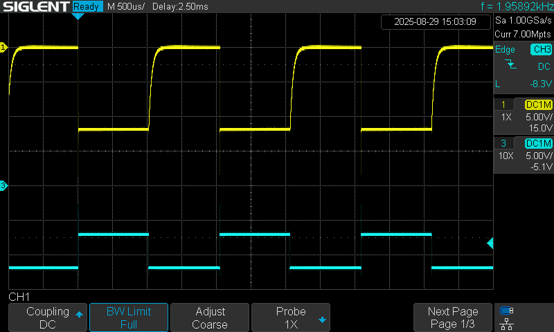
I am trying to get a pwm control circuit using two picos and master and slave. the requirement is to be able to change the frequency and duty cycle and also be operational at 12v and 24v. consequently, we have created this circuit and prototyped a pcb. but when we check, we observe a slope at the start of every pwm. why is this happening and how can I solve this? have attached the waveform shape and the schematic.
Your schematic shows multiple (40) open drain MOSFETs.
When the MOSFET is turned on, there is a low resistance to GND which makes the signal you are observing fall rapidly.
When the MOSFET is turned off, something else has to pull the drain high.
I don't see anything on your schematic that pulls the drain high.
Looking at the oscilloscope trace, I can see from the position of the Channel 1 offset indicator (arrowed below) that you have the outer of your coax. lead connected to the +12V.
I see from the 1:1 probe attenuation factor setting that you are not using a X10 probe.
This indicates to me that it is only the 1MΩ input resistance of the oscilloscope that is pulling the open drain output high.
There will be stray capacitance between the MOSFET drain and source, which together with the capacitance of the BNC lead (up to 100pF/m) and the 1MΩ form an RC circuit. This causes the slow rise time.
If you were to connect a resistor of around 1kΩ between the +12V and the open drain then the rise time of the signal will be reduced, making the trace look better.