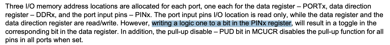
PINx toggles bits:
or
? will first variant toggle only one pin too?
Yes, but it takes more instructions, and a temporary register.
(Because the compiler will produce a single "Set Bit in IO register" instruction for the "|=" version, but the first needs to load 1<<4 into a register and then use an OUTput instruction.)
OTOH, PINB = 0xFF; will toggle ALL the pins in PORTB.
Is the interrupt for millis still running, or has the compiler optimized that away? With the tight timing, that could also be causing missed timer interrupts.
Couldn't the timer also be configured to toggle its associated output pin without the use of the interrupt?
The maximum freq that you can output to GPIO via the timer is FPU/4, so for Atmega 16 MHz it will 4 MHz square signal. But to achieve that, you MUST NOT use an interrupt to toggle a pin - the interrupt is too slow for that.
Use a hardware PWM mode.
Thanks… that’s faster than I would ever need from a micro… but if I did need it, I would just commit it to dedicated, external, discrete logic circuits…
UPDATE TO ALL : OK, I have achieved my goals in this struggle, thanks to all involved for suffering me. I can now control the TMR2 interval and toggle an output pin with an interrupt routine... It seems my code did not invoke MODE 2 ( = CTC mode ) for TMR2, as shown in table 17-8 of page 130 in this Atmel document :
CTC mode should reset the TMR2 counter to zero on interrupt, but it does not... I had to add a separate line of code inside the TMR2 ISR to clear the TMR2 counter. I also ditched my ( slow ) bit toggle code and replaced it with the much faster code, suggested by others on this forum... thanks. As a result, I was able to achieve bit toggle rates exceeding 2 MHz... far beyond what I needed... I guess I'm done here, thanks again to all... adios.
Please show your final code.
1 Like
.....
/*
Bob's Arduino AtMega 328P timer interrupt program
Timer_Interrupts_Bob.ino
BobStuff/Products/Si5351/Source
*/
// Definitions
#define OutputPin 12 // output pin for TMR0 signal
// TMR0 Interrupt Service Routine
ISR(TIMER2_COMPA_vect)
{
TCNT2 = 0; // clear TMR2 8 bit count register
PINB = 1 << 4; // toggle the output pin
}
// Startup Code
void setup()
{
pinMode(OutputPin, OUTPUT); // digital pin 12 = output
noInterrupts(); // disable all interrupts ( temporary )
TCCR2A = 0; // clear TCCR2A ( TMR2 control reg )
TCCR2B = 0; // clear TCCR2B ( TMR2 control reg )
TCNT2 = 0; // clear TMR2 8 bit count register
OCR2A = 140; // count up to 140, then INTERRUPT ( = 890 Hz bit toggle)
TCCR2A |= (1 << WGM21); // turn on TMR2 CTC mode ( ? )
TCCR2B |= (1 << CS22); // set CS22 in prescaler ( = DIV BY 64 )
TIMSK2 |= (1 << OCIE2A); // enable TMR2 COMPARE interrupt
interrupts(); // enable all unmasked interrupts
}
// Main Program Loop
void loop()
{
}
.....
My final code below generates a toggle rate of about 890 Hz... that is comparable to other equipment I have here, which I intend ( eventually ) to replace or supplement with an Arduino..... hence my work on this code.
How did you checked that ?
This is very close to Arduino standard PWM frequency - 980 Hz - so probably you don't need any specific code at all in order to generate of square wave of 980 hz
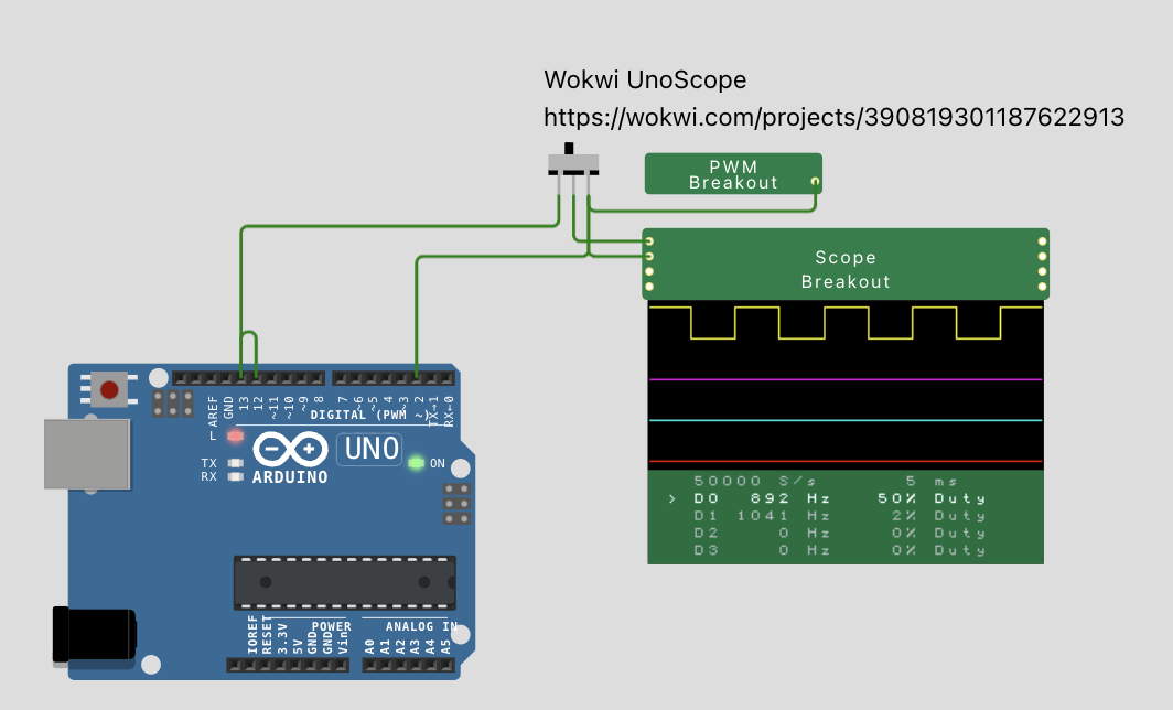
Disabling the TCNT2 = 0; and dropping it into UnoScope - Wokwi ESP32, STM32, Arduino Simulator (and shorting pins 12&13) gives 892 Hz:
/*
  Bob's Arduino AtMega 328P timer interrupt program
  Timer_Interrupts_Bob.ino
  BobStuff/Products/Si5351/Source
*/

// Definitions
#define OutputPin 12 // output pin for TMR0 signal

// TMR0 Interrupt Service Routine
ISR(TIMER2_COMPA_vect)
{
  //TCNT2 = 0; // clear TMR2 8 bit count register
  PINB = 1 << 4; // toggle the output pin
}

// Startup Code
void setup()
{
  pinMode(OutputPin, OUTPUT); // digital pin 12 = output
  noInterrupts(); // disable all interrupts ( temporary )
  TCCR2A = 0; // clear TCCR2A ( TMR2 control reg )
  TCCR2B = 0; // clear TCCR2B ( TMR2 control reg )
  TCNT2 = 0; // clear TMR2 8 bit count register
  OCR2A = 140; // count up to 140, then INTERRUPT ( = 890 Hz bit toggle)
  TCCR2A |= (1 << WGM21); // turn on TMR2 CTC mode ( ? )
  TCCR2B |= (1 << CS22); // set CS22 in prescaler ( = DIV BY 64 )
  TIMSK2 |= (1 << OCIE2A); // enable TMR2 COMPARE interrupt
  interrupts(); // enable all unmasked interrupts
}

// Main Program Loop
void loop()
{

}
The datasheet says that's how CTC mode works... it means "clear timer counter"... as for how I checked it... my code originally generated a constant frequency regardless of the value I put into the COMPARE register. ( OCR2A ) If the CTC really worked, it should reset the timer counter to zero each time it generated an interrupt... that means small values of OCR2A would cause high frequencies, and large values would generate low frequencies... but no changes to OCR2A changed the frequency at all. Apparently the counter just continued "up counting" until it rolled over to zero, then caused another interrupt when it hit the COMPARE register value again... since the TMR input clock frequency was constant and the rollover time ( 256 bit overflow ) was also constant, the output frequency also was constant... despite what the datasheet said CTC should do. The COMPARE register was generating the interrupt properly, but CTC was NOT resetting the counter to zero....
Adding a line to the ISR routine to clear the timer register ( = back to zero ) did what the CTC mode should have done,.... but didn't do... and the extra line of code made it work.
After adding that line, change to the OCR2A register DID affect the output frequency, just as it should have done, if the CTC mode really was working as the datasheet described it.
If you don't believe it, try it yourself... REM out the line in the ISR that zeros the timer register, and then try some changes to the value of OCR2A ( value = 1 to 255 ) and see how the output clock behaves... then re-enable the REM'ed line and try it again...
This was mostly a learning experience... I didn't want to take the easy path... I wanted to learn how to do this stuff myself... from scratch...
See the message #53 - @DaveX already done that. He obtained a right frequency result without your TCNT2 =0; line in the interrupt.
I also did it, not on simulator - but on real Nano board.
I'm sure that this line in the interrupt handler is not needed. I removed it and ran the code with OCR2A = 140 and got the frequency of 887Hz, as it should be.
Then I set OCR2A = 14 and ran the code again - the frequency changes to 8.33 kHz.
Conclusion - if this did not work for you - the reason is not that the CTC does not reset the counter. You probably made a mistake somewhere else - in the code or in the connections
1 Like
No clear of TCNT needed.
(The previous behavior was all due to the ISR taking too long.)
Here's my somewhat more fleshed out version.
Type a number in the Serial Monitor to change OCR2A, type P followed by a number to change the prescaler value (TCCR2B)
Heh. Changing OCR2A to a low enough number will hang the board.
/*
 * Bob's Arduino AtMega 328P timer interrupt program
 * As modified by WestfW
 */

// Definitions
char pinState = 0;
#define OutputPin 12 // output pin for TMR0 signal
#define OutPin PINB
#define OutBit (1<<4)  // Also "pin 12" PortB, pin4

// TMR0 Interrupt Service Routine
ISR(TIMER2_COMPA_vect) {
  OutPin |= OutBit;  // Writing to Pinx toggles the output
}

// Startup Code
void setup() {
  Serial.begin(115200);
  while (!Serial)
    ;
  Serial.println("\nVarial Timer Test via CTC Mode, OCR2A, and pin 12");

  pinMode(OutputPin, OUTPUT); // digital pin 12 = output

  noInterrupts(); // disable all interrupts ( temporary )
  TCCR2A = 0; // clear TCCR2A (turn off timer)
  TCCR2B = 0; // clear TCCR2B (turn off clock)
  TCCR2B = (1 << CS20); // set CS20, no prescaler ( = DIV BY 1 )
  OCR2A = 50; // count up to 50, then INTERRUPT
  TCCR2A = (1 << WGM21); // turn on TMR2 CTC mode
  TIMSK2 = (1 << OCIE2A); // enable TMR2 COMPARE interrupt
  interrupts(); // enable all unmasked interrupts
}

#define show(reg) Serial.print(#reg " = 0x"); Serial.println(reg, HEX)

// Main Program Loop
void loop() {
  if (Serial.available()) {
    if (Serial.peek() == 'P') {
      /*
       * Type Pnnn to change prescaler (TCCR2B)
       */
      Serial.read();  // discard the P
      TCCR2B = Serial.parseInt();
       Serial.print("New value ");
      show(TCCR2B);
    } else {
      /*
       * Type an intger to change compare value (OCR2A)
       */
      OCR2A = Serial.parseInt();
      Serial.print("New value ");
      show(OCR2A);
    }
    Serial.println();
  }
  show(GTCCR);
  show(TCCR2A);
  show(TCCR2B);
  show(TCNT2);
  show(OCR2A);
  show(OCR2B);
  show(TIMSK2);
  show(TIFR2);
  show(ASSR);
  show(GTCCR);
  Serial.println();
  delay(10000);
}
OK, well I’ll plead ignorance in this case,… I didn’t understand what he was trying to say…
The image shows a Uno board, the caption says it is a simulation program, and he’s shorting together pins 12 and 13… why ?
Once I saw it was a Uno board ( which I am not familiar with ) I pretty much ignored the post, thinking it was not relevant to me.
The Uno and Nano has the same MCU on board - Atmega328, and fully compatible in matter the code.
OK, I can’t comment on this… I can’t follow what you are doing here in your post… I’m too green with Arduinos and the IDE tools…
I just posted a reply to the previous comment, I am surprised he also reports the register clear was not needed…
I assure you both, it was needed here…
All I can suggest is you folks are maybe using a different kind of Nano…
Mine is a basic Nano, Atmel ATMega 328 micro… Arduino part number A000005