Clearly I am not the right person to help you. I don't have any advice significantly better or different to what I have given you. Good luck with your project, I hope you get there in the end.
Okay, I am going to try this again. I have deleted all nextion library stuff and I am now just struggling with getting multiple things sending and receiving between the arduino and the nextion. Here is my entire code.
#include <Bounce2.h>

String    endChar = String(char(0xff)) + String(char(0xff)) + String(char(0xff));

//Digital Inputs
const int Air_Pressure_OK = 22;
const int Coarse_Sys_Button = 24;
const int Mill_Sys_Button = 25;
const int Mold_Sys_Button = 26;
const int Auger_Switch = 27;
const int Coarse_Half_Limit = 28;
const int Coarse_Full_Limit = 29;
const int Powder_Full_Limit = 30;


//Analog In
const int Current_Sensor_Read = A15;
int Sensitivity = 188;
int Current_Read_Value = 0;
int offsetVoltage = 25000;
double ReadVoltage = 0;
int RealCurrent = 0;

//Digital Outputs
const int Alarm_Strobe = 42;
const int Pulsers_On_LED = 43;
const int Coarse_Blower_Relay = 44;
const int Coarse_Al_Relay = 45;              //Al is air lock//
const int Transfer_Blower_Relay = 46;
const int Millshop_Blower_Relay = 47;
const int Millshop_Al_Relay = 48;
const int Molder_Blower_Relay = 49;
const int Molder_Al_Relay = 50;
const int Coarse_Powder_Al = 51;
const int Coarse_Top_Al = 52;
const int Auger_Relay = 53;


Bounce myInputPin1 = Bounce();
Bounce myInputPin2 = Bounce();
Bounce myInputPin3 = Bounce();

//Pin State

byte All_On_Button_State = LOW;

byte Coarse_Button_State = LOW;
boolean offDelayTimer_1 = false;

byte Mill_Button_State = LOW;
boolean offDelayTimer_2 = false;

byte Mold_Button_State = LOW;
boolean offDelayTimer_3 = false;

//Times
unsigned long lastDebounce_1;
unsigned long debounceDelay_1 = 0; // Coarse System Delay Off
unsigned long lastDebounce_2;
unsigned long debounceDelay_2 = 0; // Millshop Delay Off
unsigned long lastDebounce_3;
unsigned long debounceDelay_3 = 0; //<Molder Delay Off

void setup()
{
  Serial.begin(9600);
  Serial2.begin(9600);
  //Serial3.begin(9600);

  //Set Pin IO
  pinMode(Air_Pressure_OK, INPUT_PULLUP);
  pinMode(Coarse_Sys_Button, INPUT_PULLUP);
  pinMode(Mill_Sys_Button, INPUT_PULLUP);
  pinMode(Mold_Sys_Button, INPUT_PULLUP);
  pinMode(Auger_Switch, INPUT_PULLUP);
  pinMode(Coarse_Half_Limit, INPUT_PULLUP);
  pinMode(Coarse_Full_Limit, INPUT_PULLUP);
  pinMode(Powder_Full_Limit, INPUT_PULLUP);
  pinMode(Current_Sensor_Read, INPUT);

  myInputPin1.attach(Coarse_Sys_Button);
  myInputPin1.interval(50);
  myInputPin2.attach(Mill_Sys_Button);
  myInputPin2.interval(50);
  myInputPin3.attach(Mold_Sys_Button);
  myInputPin3.interval(50);

  pinMode(Alarm_Strobe, OUTPUT);
  pinMode(Pulsers_On_LED, OUTPUT);
  pinMode(Coarse_Blower_Relay, OUTPUT);
  pinMode(Coarse_Al_Relay, OUTPUT);
  pinMode(Transfer_Blower_Relay, OUTPUT);
  pinMode(Millshop_Blower_Relay, OUTPUT);
  pinMode(Millshop_Al_Relay, OUTPUT);
  pinMode(Molder_Blower_Relay, OUTPUT);
  pinMode(Molder_Al_Relay, OUTPUT);
  pinMode(Coarse_Powder_Al, OUTPUT);
  pinMode(Coarse_Top_Al, OUTPUT);
  pinMode(Auger_Relay, OUTPUT);

  //Set Pin Status
  digitalWrite(Alarm_Strobe, HIGH);
  digitalWrite(Pulsers_On_LED, HIGH);
  digitalWrite(Coarse_Blower_Relay, HIGH);
  digitalWrite(Coarse_Al_Relay, HIGH);
  digitalWrite(Transfer_Blower_Relay, HIGH);
  digitalWrite(Millshop_Blower_Relay, HIGH);
  digitalWrite(Millshop_Al_Relay, HIGH);
  digitalWrite(Molder_Blower_Relay, HIGH);
  digitalWrite(Molder_Al_Relay, HIGH);
  digitalWrite(Coarse_Powder_Al, HIGH);
  digitalWrite(Coarse_Top_Al, HIGH);
  digitalWrite(Auger_Relay, HIGH);
}

void loop()
{
  //if(Serial2.available()){
    //String dfd = "";
    //delay(30);
    //while(Serial2.available()){
    //  dfd += char(Serial2.read());
    //}
   // if(dfd.length()>15) dfd="";
   // if(dfd.substring(0,3)=="val" & (dfd.length()==15)){

   // dfd="";
   // }


  myInputPin1.update();
  myInputPin2.update();
  myInputPin3.update();

//Coarse Button
  if ((myInputPin1.fell() && Coarse_Button_State == LOW )or(All_On_Button_State == HIGH))
  {
    digitalWrite(Coarse_Blower_Relay, LOW );//instant turn on
    digitalWrite(Coarse_Al_Relay, LOW );
    digitalWrite(Transfer_Blower_Relay, LOW );
    digitalWrite(Coarse_Powder_Al, LOW );
    digitalWrite(Coarse_Top_Al, LOW );

    Coarse_Button_State = HIGH;
    //Serial.println("Coarse_On");
}

  else if ((myInputPin1.fell() && Coarse_Button_State == HIGH)or(All_On_Button_State == LOW))
  {
    offDelayTimer_1 = true;
    lastDebounce_1 = millis();
  }

  if (offDelayTimer_1)
  {
    if (millis() - lastDebounce_1 >= debounceDelay_1)
    {
      digitalWrite(Coarse_Blower_Relay, HIGH );//delay turn off
      digitalWrite(Coarse_Al_Relay, HIGH );
      Coarse_Button_State = LOW;
      //Serial.println("Coarse_Off");
      offDelayTimer_1 = false;
      if(Mold_Button_State == LOW && Mill_Button_State == LOW)
      {
          digitalWrite(Transfer_Blower_Relay, HIGH );
          digitalWrite(Coarse_Powder_Al, HIGH );
          digitalWrite(Coarse_Top_Al, HIGH );
      }
    }
  }

  // MILLSHOP BUTTON
  if ((myInputPin2.fell() && Mill_Button_State == LOW )or (All_On_Button_State == HIGH))
  {
    digitalWrite(Millshop_Blower_Relay, LOW );//instant turn on
    digitalWrite(Millshop_Al_Relay, LOW );
    digitalWrite(Transfer_Blower_Relay, LOW );
    digitalWrite(Coarse_Powder_Al, LOW );
    digitalWrite(Coarse_Top_Al, LOW );

    Mill_Button_State = HIGH;
    //Serial.println("MillShop_On");
  }

  else if ((myInputPin2.fell()  && Mill_Button_State == HIGH)or (All_On_Button_State == LOW))
  {
    offDelayTimer_2 = true;
    lastDebounce_2 = millis();
  }

  if (offDelayTimer_2)
  {
    if (millis() - lastDebounce_2 >= debounceDelay_2)
    {
      digitalWrite(Millshop_Blower_Relay, HIGH );//delay turn off
      digitalWrite(Millshop_Al_Relay, HIGH );
      if(Coarse_Button_State == LOW && Mold_Button_State == LOW)
      {
         digitalWrite(Transfer_Blower_Relay, HIGH );
          digitalWrite(Coarse_Powder_Al, HIGH );
          digitalWrite(Coarse_Top_Al, HIGH );
      }
      Mill_Button_State = LOW;
      //Serial.println("MillShop_Off");
      offDelayTimer_2 = false;
    }
  }

//Molder Button
  if ((myInputPin3.fell() && Mold_Button_State == LOW)or(All_On_Button_State == HIGH))
  {
    digitalWrite(Molder_Blower_Relay, LOW );//instant turn on
    digitalWrite(Molder_Al_Relay, LOW);
    digitalWrite(Transfer_Blower_Relay, LOW );
    digitalWrite(Coarse_Powder_Al, LOW);
    digitalWrite(Coarse_Top_Al, LOW);

    Mold_Button_State = HIGH;
    //Serial.println("Molder_On");
  }

  else if ((myInputPin3.fell()  && Mold_Button_State == HIGH)or (All_On_Button_State == LOW))
  {
    offDelayTimer_3 = true;
    lastDebounce_3 = millis();
  }

  if (offDelayTimer_3)
  {

    if (millis() - lastDebounce_3 >= debounceDelay_3)
    {
      digitalWrite(Molder_Blower_Relay, HIGH );//delay turn off
      digitalWrite(Molder_Al_Relay, HIGH );
      if(Coarse_Button_State == LOW && Mill_Button_State == LOW)
      {
          digitalWrite(Transfer_Blower_Relay, HIGH );
          digitalWrite(Coarse_Powder_Al, HIGH );
          digitalWrite(Coarse_Top_Al, HIGH );
      }
      Mold_Button_State = LOW;
      //Serial.println("Molder_Off");
      offDelayTimer_3 = false;
    }
  }

  if  (digitalRead(Coarse_Half_Limit)== LOW or digitalRead(Auger_Switch)== LOW)
  {
    digitalWrite(Auger_Relay, LOW);
  }

  else
  {
    digitalWrite(Auger_Relay, HIGH);
  }

  if (digitalRead(Coarse_Full_Limit)==LOW or digitalRead(Powder_Full_Limit) == LOW)
  {
    digitalWrite(Alarm_Strobe, LOW);
  }
  else
  {
    digitalWrite(Alarm_Strobe, HIGH);
  }
  if (digitalRead(Air_Pressure_OK) == LOW)
  {
    digitalWrite(Pulsers_On_LED, LOW);
  }
  else
  {
    digitalWrite(Pulsers_On_LED, HIGH);
  }

  Current_Read_Value = analogRead(Current_Sensor_Read);
  ReadVoltage = (Current_Read_Value)*50000/1024;
  RealCurrent = ((offsetVoltage - ReadVoltage)/Sensitivity);
     //if (digitalRead(Auger_Relay == LOW)& RealCurrent != Current_Read_Value){
     Serial.print("p[2].n9.val=" + String(RealCurrent));
     Serial.write(0xff);
     Serial.write(0xff);
     Serial.write(0xff);
     delay(50);
     //}
     //else if (digitalRead(Auger_Relay== HIGH)){
     //delay(500);
     //Serial.print("p[2].n9.val= 0");
    // Serial.write(0xff);
     //Serial.write(0xff);
     //Serial.write(0xff);
     //delay(50);
     //}

  if(Serial2.available()){
    String data_from_display = "";
    delay(30);
    while(Serial2.available()){
      data_from_display += char(Serial2.read());
    }
    if(data_from_display == "Pon")
    {
      All_On_Button_State = HIGH;
      Serial.println("All ON Activated");
    }

    if(data_from_display == "Poff")
    {
      Serial.println("All Off Activated");
      delay(15000);
      All_On_Button_State = LOW;
      }
  }
}
This is the portion I am focused on now.
//Section One

Current_Read_Value = analogRead(Current_Sensor_Read);
  ReadVoltage = (Current_Read_Value)*50000/1024;
  RealCurrent = ((offsetVoltage - ReadVoltage)/Sensitivity);
     //if (digitalRead(Auger_Relay == LOW)& RealCurrent != Current_Read_Value){
     Serial.print("p[2].n9.val=" + String(RealCurrent));
     Serial.write(0xff);
     Serial.write(0xff);
     Serial.write(0xff);
     delay(50);
     //}
     //else if (digitalRead(Auger_Relay== HIGH)){
     //delay(500);
     //Serial.print("p[2].n9.val= 0");
    // Serial.write(0xff);
     //Serial.write(0xff);
     //Serial.write(0xff);
     //delay(50);

 //}

// Section Two

  if(Serial2.available()){
    String data_from_display = "";
    delay(30);
    while(Serial2.available()){
      data_from_display += char(Serial2.read());
    }
    if(data_from_display == "Pon")
    {
      All_On_Button_State = HIGH;
      Serial.println("All ON Activated");
    }

    if(data_from_display == "Poff")
    {
      Serial.println("All Off Activated");
      delay(15000);
      All_On_Button_State = LOW;
      }
  }
}
So, if I set both sections that reference serial, to serial0, neither section works. And if I set both sections to serial2, neither section works. BUUUUUT if I set the analog read section or section one to serial0, it works but the second section does not work. And then if I set the second section to serial2, it will work but the first section will not work.
I cannot get both sections to work at the same time. My suspicion is that both sections are fighting for room in the serial port.
How do I send one section, then the next, then check back for the first over and over again.
Bear in mind, I still have a third section to get working, but I will cross that bridge once I have built these two.
//EDIT//
Yes both serial0 and serial 2 have been initialized,
void setup()
{
  Serial.begin(9600);
  Serial2.begin(9600);
//Serial3.begin(9600);```Which serial port is the Nextion connected to? Which pins? The serial ports on the Mega are
Serial (port 0 used for the serial monitor)
Serial1 (port 1 on pins 18 Tx, 19 Rx)
Serial2 (port 2 on pins 16 Tx, 17 Rx) (Your setup code suggests you are using this one for the Nextion, is this the case?)
Serial3 (port 3 on pins 14 Tx, 15 Rx)
You seem very confused about which serial port does what and what you are sending to them. You can send to any of the 4 serial ports at any time in your code and the hardware will take care of it. I don't know what any of this means:
If I set both sections that reference serial, to serial0, neither section works. And if I set both sections to serial2, neither section works. BUUUUUT if I set the analogue read section or section one to serial0, it works but the second section does not work. And then if I set the second section to serial2, it will work but the first section will not work.
What does 'work' and 'not work' mean? What do you want to happen, what actually happens and how is that different to what you want to happen?
You need to be clear about which serial port is for what purpose and stick to it.
Two important things:
Do things in small steps
Stop trying to do all your code in one go. Get on little bit working correctly then start on the next little bit and get it working with the first bit. Trying to do the whole thing in one chunk as you seem to be doing doesn't work for experienced programmers and certainly won't work for a beginner.
Use functions
If you look at my code the only thing in loop() is
void loop() {
  HMI_read();
  clock_run();
}
Everything else is in separate functions. Putting everything in loop() makes it very difficult to follow and very difficult to debug. Functions should have a name that describes what they do. I know that a lot of example code has everything in loop, but it's not good practice and I wish they didn't do it. My example code is never like that even for something very simple.
I suggest you start with a simple sketch that reads the analogue input. The code should be in a separate function called from loop() and should do the following:
-
Have a timer so it does its read thing only ever so often, I don't know how often but maybe twice per second (you can change it later). Do not use delay, have a read of Using millis for timing and look how my function clock_run() makes the clock increment once per second.
-
Once read the value should be saved in a global variable for later use by other code.
-
As well as saving the value also have a global flag, which should be of type bool, which indicates that the global variable has been updated with new data.
-
In order to check everything works also use Serial.print() to send the value read to the serial monitor so you can see that it is what you expect.
Once the above is working write another function, also called from loop(), which sends the newly read data to a text box on the Nextion. This function should check the flag mentioned above, set it to false and send the data to the Nextion.
At no point use delay() for anything. Do not use Strings (capital S),they cause problems, and in any case, as I don't use them I am not familiar with them so as soon as I see them in your code I don't know it will work at all.
From reading your code I strongly suspect you still do not understand the basics and have not properly read the tutorials.
If you don't understand the above ask questions about the bits you don't understand.
If you find my way of explaining things does not work for you then consider if you want me to continue to help you, my way of teaching might not be right for your way of learning, there is no shame in admitting this.
Good luck.
Serial port 0 will be eliminated as soon as the project is running. I am simply using it to see if the communication was actually sent. They are in fact being sent.
What I need:
- The real current value (Line 276 and 278) to send real time, to the amp screen in the Nextion. It currently only works with serial 0. If I change to serial2, it does not work. Regardless of section 2.
- I need the dual state button to change the state of the all_on_button_state.(Lines 293 thru 309) It currently only works with serial2. If I change it to serial 0, it does not work.
If both sections, aptly labeled, section one and section two, are set to use the same serial port, both sections do not work at the same time. If I use serial 2, section 2 works. As long as I am connected to serial 2, (pins 16 and 17). However section one does not work while set serial 2 and connected to serial 2.
If I use serial 0 and set both sections to serial 0 and connect to serial 0(Pins 1 and 0), only section one will work. Section two will not work. It does not even transmit.
I appreciate your advice on the moving material out of the loop. As soon as I have the code working properly and sending multiple items over the same serial port simultaneously, I will certainly look into doing that. It was however my understanding, that anything in setup is only ran once at start up. So how can I check if a button was pressed, an infinite amount of times in the setup?
Again thank you for your help.
The point of moving code to smaller functions is to make it easier for you to understand and debug now, not to polish it up afterwards.
Do you feel as though that is the reason for the serial communication issues? If so I will try to do so right now. I just do not have that luxury to polish anything with a deadline approaching. If I had a second monitor connected, and one monitor only dealt with section one of my code and the other monitor only dealt with section two of my code, everything would be fine. So I am lost at how moving code that works will solve the communication problem?

This is a prototype. This is not a finished product. The finished product is contactors instead of relays, controlling 480v three phase. 1000 horsepower motors instead of 5v dc motors. The MCU will be replaced by PLC with up to 20 input and output cards. Communication will be replaced by ethernet cables with modbus and profibus protocol. The limit switches will be replaced with industrial grade IR sensors. The entire system spans a city block across three levels of a multi story building. The cabinet for the real project will not be plexi-glass and a wood frame. It will be 72x72x18inch industrial IEC rated cabinet. The on/ off toggle switch will be a 200amp service disconnect. The monitor itself will be a cloud based virtual SCADA system accessible from any internet or cellular platform.
Folks, I am begging you to understand that this is just a prototype for a school project. Absolutely nothing more.
It doesn't directly, it just makes it easier to work with your code and that makes it easier to debug.
So while, I am rewriting 310 lines of code and rewriting every single function in my code, is there any one that could maybe offer some insights as to how I am supposed to get one serial port to both send and receive items through the serial port simultaneously?
As @PerryBebbington asked earlier, which serial port is the Nextion connected to?
It looks like you're sending data intended for the Nextion to serial e.g.
     Serial.print("p[2].n9.val=" + String(RealCurrent));
     Serial.write(0xff);
     Serial.write(0xff);
     Serial.write(0xff);
Or at least I infer that from those 0xff characters.
But you're trying to get data from the display on Serial2.
I'm confused.
Post 45 explains everything I think. If not I am trying to figure out how to post a video to hear. If I set both to serial 0 and connect to serial 0 only section one works. But if I set both to serial 2 and connect to serial 2, only section two works. I am not hung up on which serial port I want to use. I have all four initialized. I just need all sections to work at the same time on one serial port. Unless Nextion perhaps has the ability to send and receive over multiple ports?
can we do videos on here or only images?
Often, people use Youtube for the video & link to it. That and GitHub are about the only external sites the folks helping you will visit.
But again, which serial port is connected to the display? I'm beginning to suspect you've wired it so that one port's TX line goes to the Nextion but you've got RX on a different port. How is it actually wired?
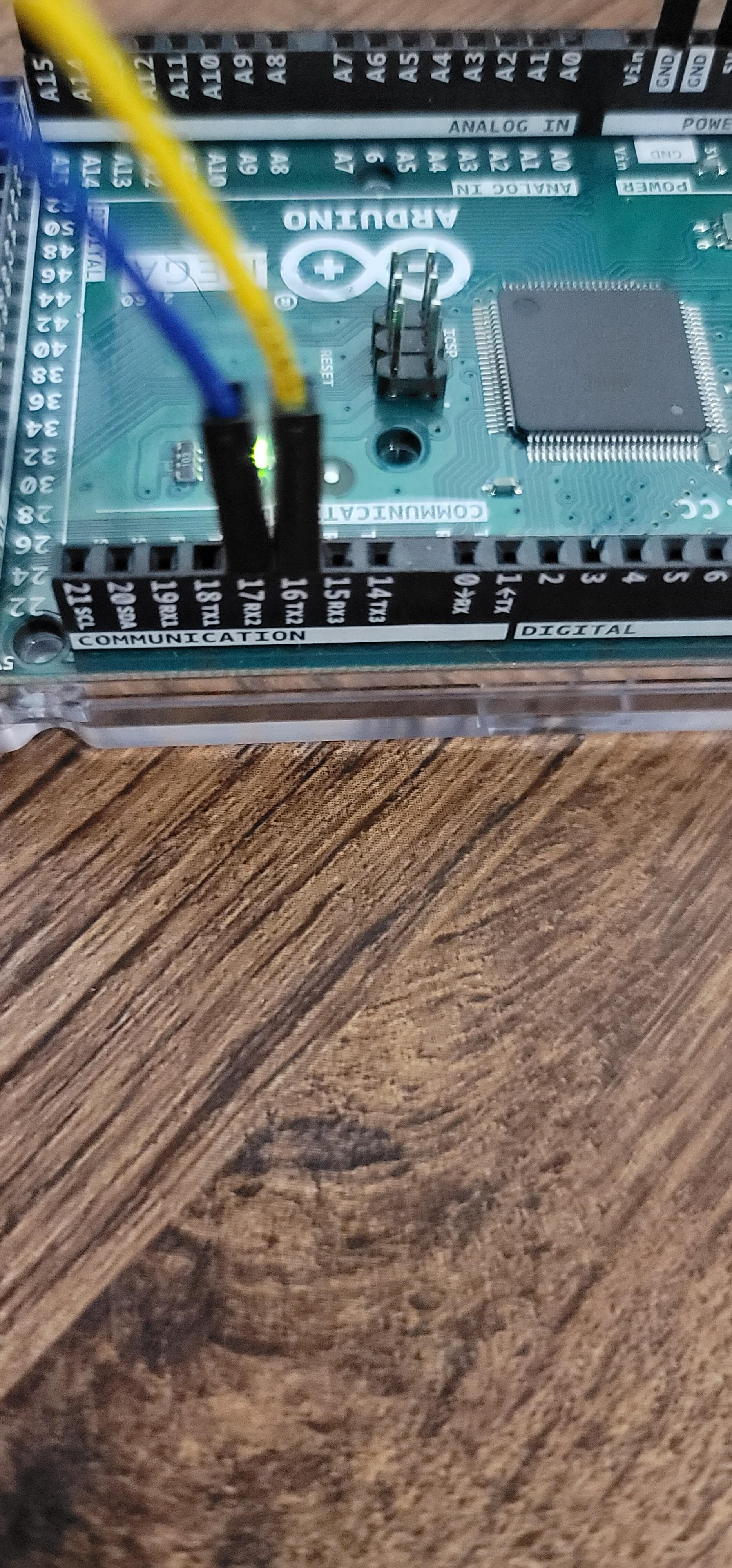
Ah I see what you are asking. I have yellow wire from nextion, RX, going to pin txt2 pin 16 on the arduino. I have blue wire from nextion TX, going to pin 17 rx2 on the arduino. From my pin mapping page I downloaded, that should be serial2.
Now as connected, section two works but section one does not work.
What about serial? How is it wired? I find it rather perplexing that printing stuff there apparently finds its way to the display.

That's bizarre. You should see the results of this:
Serial.print("p[2].n9.val=" + String(RealCurrent));
     Serial.write(0xff);
     Serial.write(0xff);
     Serial.write(0xff);
On the serial monitor only. Are you convinced that it shows up on the Nextion?
Please watch.
https://youtu.be/1ndz9b_HHB4
It is under five minutes long and shows both scenarios I have mentioned. I apologize for the times while I am adjusting my focus. I do not have auto focus cameras.
As you know, I have no experience with Nextion, but your issue here is one of debugging so maybe I can help.
I suggest that you go back to serial2 for the display. In what you're calling section two, echo everything that comes from serial2 to serial. Hopefully it will be enlightening.
Okay I will try that. Thank you.
Another thought: You're not doing your Arduino any favors by rewiring circuits with it powered up. I think you may have blown the TX pin on Serial2. Perhaps power it down and try serial3, or another Arduino if you have one.
I suspect that Serial is still ok, but the failure there is because when you set the Auger field, the Nextion sends back four bytes that represent "Instruction Successful". That means you will see that pre-pended to "Pon", so you never realize that the button on the GUI was pressed.
While you're at it, can you upload your HMI file? I think you'll have to zip it so that the forum software won't reject it.