Hello, i am looking for a way to test MAX-485 using arduino , i do not have any idea how to do it , anyone can help me?
What will you test?
RS485=>USB dongle and putty or Arduino IDE serial monitor?
Attach the line sender at TX and the receiver at RX as required for proper operation. Then enable both sender and receiver at the same time and receive whatever you send to the same Serial port. This is called a loopback test.
sorry idk what is dongle and putty but simply i want to find a way to test the IC and to check if it is working or not.
for rs-485 it can not transmit and receive at the same time, however can u explain more? sorry i am still learning
Why not?
it supports only half duplex communication.
1 Like
Can you explain how this works in half duplex with only 2 wire A and B who switch the polarity for transmitting 0 or 1. A third GPIO is needed to activate the MAX(3)485 or similar in transmitting mode.

Typical schema with MAX(3)485.
yes i know about the USB to RS485 adapter , about the Putty i will study it now but what else do i need?
What means that only one device can send at the same time. No restriction to sending to itself and any number of other receivers.
What do you think is the reason for two separate enable pins for transmitter and receiver?
Why not find out yourself?
Great! and the terminals (A and B) will be connected to the pc using the adapter or USB to RS485, what to do next?
All i know about that ic from the datasheet that it can only transmit or receive in one time , not both at the same time but i will search more for that, however the main problem here is how to test the ic.
Hello, you can use a second MAX485 that you connect to pins A and B. Then with another Arduino you watch what is happening on the UART link.
I don't know all the specs but personally I've done this with MAX232s and it works.
Then it's the best time to learn more. But if you think that you know more than I do then I can stop helping you immediately.
Ok that is a good idea and to swap the two ICs to test the receiving terminal and the transmitting terminal, but how to do that , i mean the code and the other steps?
No need to get annoyed we all learn from each others and again this is not the main issue here.
1 Like
Starting de ARduino IDE and opening the serial monitor with the correct com port and baudrate. If the Arduino transmit, you see the transmitted characters. If you put text in the input field en transmit it to the Arduino in receive modus it must be do the things that it must do.
Same for Putty. Start it.
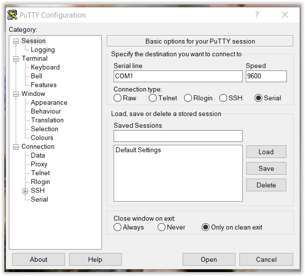
Choose Serial, right com port and right baudrate. Click Open. Then you have a terminal opened.
1 Like
You can write your code as if you were doing a simple UART link between 2 Arduinos.
Arduino1 -> UART -> MAX4485 -> RS485 -> MAX485 -> UART -> Arduino2
I have attempted something like this recently using the two additional UART's available on an ESP-32. This should allow 1 mcu to simulate 2 nodes.
However I don't think the max485 is 3.3v tolerant.