So, I have a project and I don't really know how to externally power this project.
Here's the list of all things I have in my project:
Arduino Uno
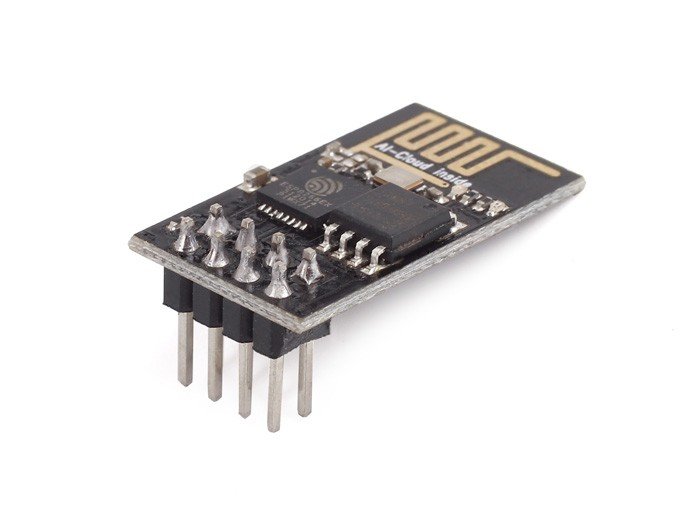
ESP-8266 (ESP 01) Wifi Module that I connect to Arduino Uno
MQ-2 Sensor
LM-35 Sensor
3 LEDs
1 Buzzer
I want to externally power (rather than via USB). I have looked on the internet for ideas, but I am not sure which one to choose. I discovered that I could power the Arduino Uno with a 9V or 4xAA battery connected to the Vin pin in Arduino Uno. However, it appears that the ESP-8266 requires power from somewhere other than the Arduino Uno.
Does this mean I'll have to power the Arduino Uno, MQ-2, LM-35, LED, and Buzzer with 4xAA batteries? And 2xAA batteries to power the ESP8266 itself?
Can I just power the entire project with only one source of power?
I am sorry for my terrible English. But I hope you understand.
That will be the problem because that contains a heater that consumes the bulk of the current so depending on the capacity of the battery you choose it will only run a short time. Remember this sensor needs to run for at least 24 hours before it starts to give reliable readings.
Do not use the onboard voltage on the Uno because it has very little power capacity. Use an external buck regulator to derive your 5V and connect it to the UNO’s 5V pin.
It's a long time since I used an ESP-8266, but am I right in thinking it's a processor in its own right, that's actually more powerful than an Uno? If that's the case (and it's very possible I have the wrong end of the stick here) could you not do all the work in the ESP and lose the Uno?
An Arduino UNO does not in any respect "supply power". It requires a 5 V supply to operate. So you need a 5 V power supply to power the UNO, and you would use that power supply also to power an ESP82566 module.
Except ...
Very bad idea.
Still bad.
Here's the "except":
Now you are on to it! If you have an ESP8266 which is a vastly more powerful processor, you do not need an Arduino, least of all the inconvenient UNO. If you require more I/O, you use "port expanders". As it is 3.3 V, you will have a bit of fun interfacing it to things that are 5 V based.
But until leftmebehind provides genuine information about his(?) proposed project, there is no point explaining further. Batteries are probably not a practical power source from what we have heard so far.
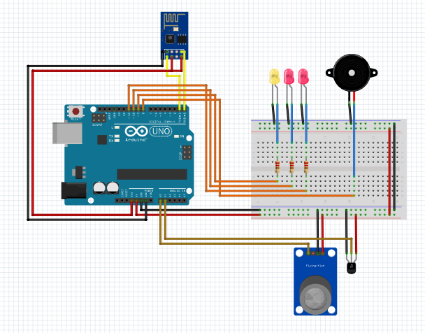
What should I do to externally power them? Or maybe did I do something wrong with my circuit (since I don't really know how to interface the ESP module with Arduino Uno)? I am looking further to your responses.
You need a diode and a pullup resistor to interface the TxD of the UNO to the Rx of the ESP-01 as it is a 3.3 V logic device. Similarly. I don't think connecting RxD of the UNO to Tx of the ESP is actually a good idea.
I believe the genuine 3.3 V regulator on a real UNO can actually supply sufficient current to operate the ESP-01, so that will probably work, though a 470 µF capacitor across the 3.3 V might be a good idea.
Best way to power it is with a USB "phone charger".
And I don't like the idea of using a UNO. A WeMOS D1 Mini and a DS18B20 instead of the LM35 would be far easier.
I won’t do that at all. From the TX of the uno you need to cut down the 5V to 3v3 so that will be a potential divider with a 510R and a 1K resistor. On the TX of the ESP-01 you need to boost the signal from 3V3 to 5V. This is best done by using two of the inverting buffers in a 75HCT14. You might see others say this is not needed but without it is not sure to work.
Well it is a physical layout diagram and quite poor at that. Nothing I has labels.
It all depends on how you want to play it. You seem to be quite short on input / outputs on that ESP so you will need some sort of port expansion, possibly at 5V. It is altogether a different project.
If you stick with the configuration you have then you will need some sort of switching to ensure you can program each processor. Something that you can’t do with the circuit as it stands. Quite honestly I wouldn’t start from here.
I would advise you use one ESP board but one with a lot more free pins than you have here.
You still haven't explained your project.
What is the purpose of the ESP8266-01 module?
Note: Using Fritzing will reduce the pool of folks prepared to even look at your problem. Please draw a schematic.
If you are only using the ESP as a WiFi "shield" for the Uno, I will quote my favorite robot: "This will all end in tears. I just know it."
You could use a Wemos D1 Mini (no Uno and no ESP8266-01), but it has only one analog port, but you could use a DS18B20 for the temperature- no analog port required.
I have never used an ESP32 board, but they have more analog ports than the Wemos.
No because with a diode in series you can only pull the input down to 0.7V.
And a 1K pull up is a slower response than my suggested values of potential divider solution.