I already connected two wires to my Prototyping Board which I want to connect to GND and 5,5V. But how do I connect my resistors and other stuff to get power? Is it like with the breadboard: The complete row of where I soldered those GND and 5,5V wires onto serve as Power and Ground? Or do I have to connect everything on the back of the board, by soldering it together?
I already connected two wires to my Prototyping Board which I want to connect to GND and 5,5V
There is no 5.5V on an arduino. There is only 3.3V and 5.0V
But how do I connect my resistors and other stuff to get power?
Good question. The answer is why I use the other board. It has power bus rows which your board does not have. You can see them in the middle and on the sides.
Is it like with the breadboard: The complete row of where I soldered those GND and 5,5V wires onto serve as Power and Ground? Or do I have to connect everything on the back of the board, by soldering it together?
You have to connect everything on the back of the board because you did not choose the kind of board I use.
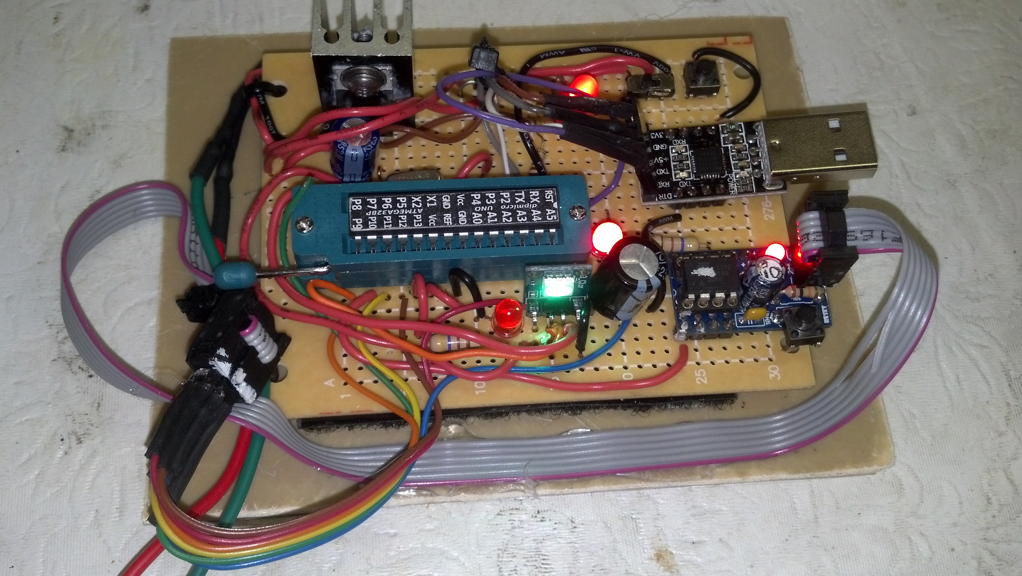
The circuit below illustrates how putting the wires through from the top of the board actually makes construction easier because all you have to do is solder it on the bottom side and clip off the excess. If you run point to point on the bottom you can't put the wires through the holes because there is no copper pads on the top of the board. If I need it to look really neat I will run point to point on the bottom but the only disadvantage is there is nothing to hold the end of the wire in place while you are waiting for the solder to cool so you have to use tweezers or needle nose pliers.