If the I2C doesn't work, let us know.
Get a low-cost Logic Analyzer from Amazon. They plug into your PC with USB and there's free software available that can do protocol decoding.
I finally managed to test this today. I removed two 0R resistors that were connecting the IC with MCU and connected A4 (data) and A5 (clk) Arduino nano pins there. I confirmed that those pins on Arduino have connection with corresponding pins on the IC (12 and 13). I also connected GND pin from AVR to GND pin of Arduino and 5V to 5V. So Arduino gets also correctly powered up by the AVR itself, even without USB.
First I tried I2C scanner, no luck. I think it hangs on begin transmissions because I waited for 5 minutes, it was stuck on Scanning... then I turned off the AVR and I got "Unkwnown error at address 0x1" which means it was stuck on first address all the time.
Then I wrote my own program for it:
const uint8_t clockPin = A4;
const uint8_t dataPin = A5;
const uint8_t bitOrder = MSBFIRST;
const uint8_t chipAddress = 136;

void writeBitToIc(uint8_t _dataPin, uint8_t _clockPin, bool _state)
{
  if (_state == true)
    digitalWrite(_dataPin, HIGH);
  else
    digitalWrite(_dataPin, LOW);

    delayMicroseconds(5);

    digitalWrite(_clockPin, HIGH);
    delayMicroseconds(5);
    digitalWrite(_clockPin, LOW);
    delayMicroseconds(5);
}

void writeByteToIc(uint8_t _dataPin, uint8_t _clockPin, uint8_t _bitOrder, uint8_t _val)
{
	uint8_t i;

	for (i = 0; i < 8; i++)  {
		if (_bitOrder == LSBFIRST)
			digitalWrite(_dataPin, !!(_val & (1 << i)));
		else
			digitalWrite(_dataPin, !!(_val & (1 << (7 - i))));

                delayMicroseconds(5);

               digitalWrite(_clockPin, HIGH);
               delayMicroseconds(5);
               digitalWrite(_clockPin, LOW);
               delayMicroseconds(5);
	}
}

void writeToIc(uint8_t _address, uint8_t _data)
{
  writeBitToIc(dataPin, clockPin, true); // start bit
  writeByteToIc(dataPin, clockPin, bitOrder, chipAddress); // chip address
  writeBitToIc(dataPin, clockPin, true); // separate bit
  writeByteToIc(dataPin, clockPin, bitOrder, _address); // select address
  writeBitToIc(dataPin, clockPin, true); // separate bit
  writeByteToIc(dataPin, clockPin, bitOrder, _data); // data
  writeBitToIc(dataPin, clockPin, true); // stop bit
}

void setup() {
  pinMode(clockPin, OUTPUT);
  pinMode(dataPin, OUTPUT);

  digitalWrite(clockPin, LOW);
  digitalWrite(dataPin, LOW);

  writeToIc(0, 64); // set Lch volume to 0.0 dB
}

void loop() {
  writeToIc(0, 64); // set Lch volume to 0.0 dB
  writeToIc(1, 64); // set Rch volume to 0.0 dB
  //writeToIc(2, 64); // set Cch volume to 0.0 dB
  //writeToIc(3, 64); // set LSch volume to 0.0 dB
  //writeToIc(4, 64); // set RSch volume to 0.0 dB
  //writeToIc(5, 64); // set LBch volume to 0.0 dB
  //writeToIc(6, 64); // set RBch volume to 0.0 dB
  //writeToIc(7, 64); // set SWch volume to 0.0 dB

  writeToIc(8, 7); // set input selector to INPUT 7 (media player)
  //writeToIc(8, 5); // set input selector to INPUT 5 (CBL/SAT)
  writeToIc(10, 80); // set Lch and Rch input selector to 8-Input

  delayMicroseconds(50000000);
}
I borrowed a Bus Pirate v3 and used it to capture the output of my Arduino, it looks legit:
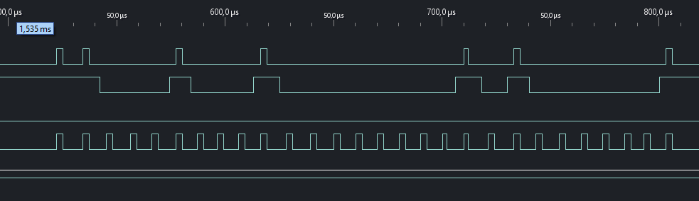
This productes:
1 | 1 0 0 0 1 0 0 0 | 1 | 0 0 0 0 0 0 0 0 | 1 | 0 1 0 0 0 0 0 0 | 1
Exactly as needed to set Lch volume to 0.0 dB by the datasheet.
So I run this code on the Arduino connected to the IC aaaaand - nothing happens. I connected AC meter to the speaker output and touched the input terminals with my hands. It's a 140 W amplifier so it should generate a lot of AC voltage when touching inputs. But nothing, zero. When I touch inputs directly to power amp, after this IC, I get some small voltage. I confirmed that months ago when I connected the actual speaker and a very quiet "brum" could be heard on touching those inputs.
Do you see anything wrong with my code or this just won't work and I should give up?
Please label the traces in that timing diagram.
If the bus is I2C or I2C-like, then the data / clock lines must be open collector with pullup resistors. Instead you're pulling them hard either HIGH or LOW. That could mess things up if the slave is trying to ACK. There is some code out there for bit banging I2C on an AVR. As I recall, it uses direct port manipulation to switch the pin between OUTPUT (to drive it low) and INPUT (to drive it to HIGH-Z). Maybe search around for that example.