Arduino Nano
I had 2 MCP23017 i/o expanders in my life
The first one was a month ago and i remember not surely that i tested it on a breadboard and it work but after some time I accidetaly connected to 10V(because of a variable step down) and then after some tests and moving it to breadboard and i watched carefuly for every connection, still didn't work at all, i also got random voltages at some pins
Then i bought the secound MCP23017 and directly connect it to my prefboard and again watch carefuly for every connection,
~pin #12 of the expander to Analog 5 (i2c clock)
~pin #13 of the expander to Analog 4 (i2c data)
~pins #15, 16 and 17 of the expander to ground (address selection)
~pin #9 of the expander to 5V (power)
~pin #10 of the expander to ground (common ground)
~pin #18 through a ~10kohm resistor to 5V (reset pin, active low) or even without the resistor
then, i connected 28 to a simple button, 27,26,25 to some switchs (then to ground)
Power it up, NO MOVEMENT, Nothing ...
Connect it to the breadboard, stop using Adafruit MCP23017 library and use this code
#include "Wire.h"

void setup()
{
 Wire.begin(); // wake up I2C bus
// set I/O pins to outputs
 Wire.beginTransmission(0x20);
 Wire.write(0x00); // IODIRA register
 Wire.write(0x00); // set all of port A to outputs
 Wire.endTransmission();
}

void loop()
{
  Wire.beginTransmission(0x20);
  Wire.write(0x12);      // address bank A
  Wire.write((byte)0xAA);  // value to send - all HIGH
  Wire.endTransmission();
  delay(500);
  Wire.beginTransmission(0x20);
  Wire.write(0x12);      // address bank A
  Wire.write((byte)0x55);  // value to send - all HIGH
  Wire.endTransmission();
  delay(500);
}
I connected only 1 led to a random pin of the expander, then to ground
And nothing :o
There is any so i can test the expander if is broken or not, using multimeter, arduino or anything else ?
Did you remember pull-up resistors on SDA and SCL? If not, it won't work, at least not reliably. Use 4.7K-10K resistors to pull up the to I2C wires to +5V.
I don't know of a way to programmatically check if the IO expander is working/responding, but that could be nice. However, the MCP23017 is usually so robust and easy to use, that it's hardly necessary.
RuneJ:
Did you remember pull-up resistors on SDA and SCL? If not, it won't work, at least not reliably. Use 4.7K-10K resistors to pull up the to I2C wires to +5V.
I don't know of a way to programmatically check if the IO expander is working/responding, but that could be nice. However, the MCP23017 is usually so robust and easy to use, that it's hardly necessary.
Tnx for your respond man
i didn't forgot about them, i used 10k resistors
Looking at this image, I suspect you may have made a pin counting error. It looks like SDA (A4) is connected to pin 14 (should be 13), and SCL (A5) is connected to pin 13 (should be 12).
I haven't checked the other connections, but I'll leave that to you.
i already checked the pins to many times that i know them with closed eyes
if the i2c scanner got no signal that mean the expander is ded ?
The next big problem is that when i'll buy another one, the new one will break just like this one does, for no reason, can arduino be damaged so it damage the expander too?
i also have a lcd with i2c witch works great
Ah, sorry. Pin 14-15 were hidden by the Nano in the first picture.
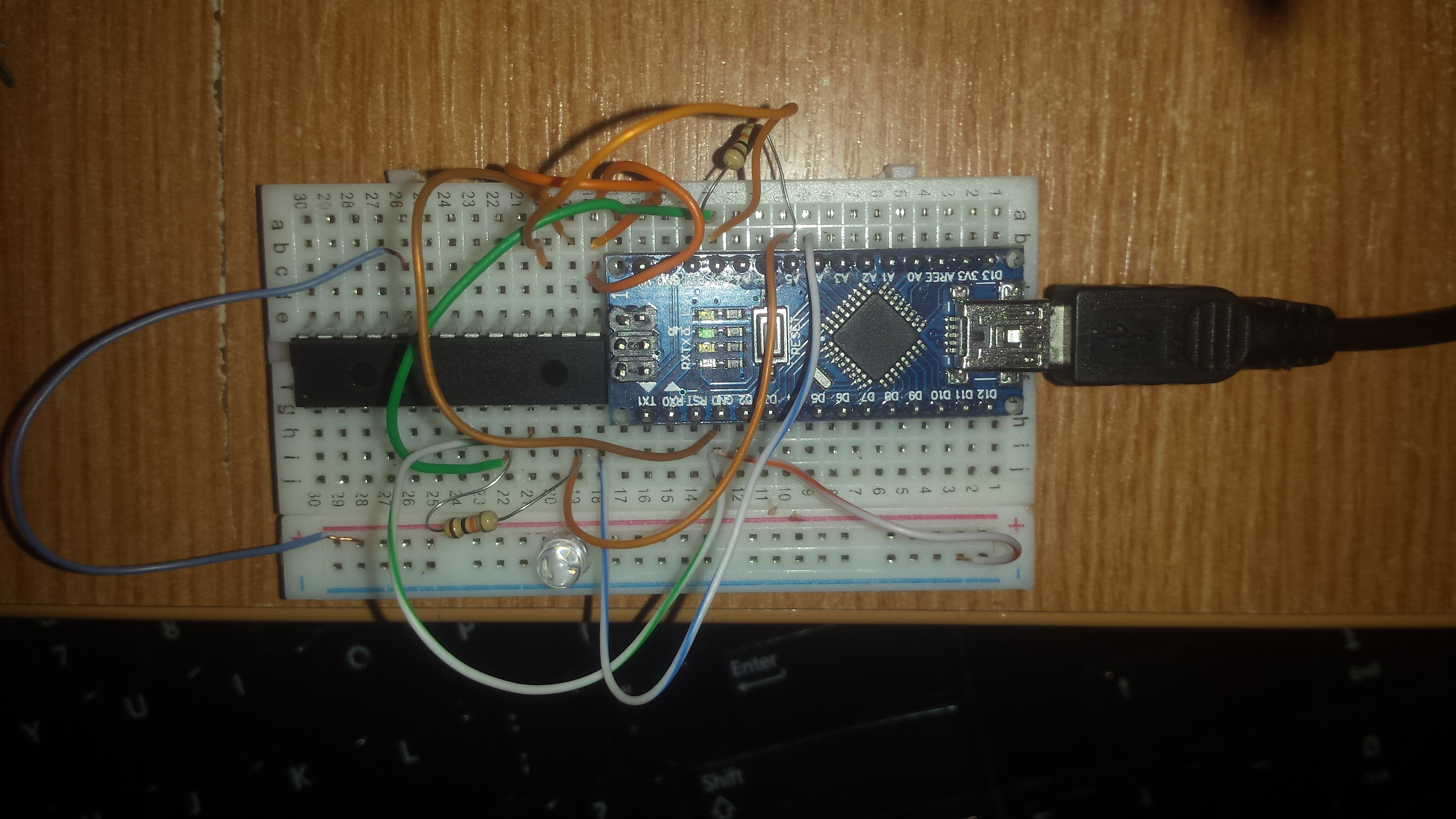
Well, if you're aboslute certain about the wiring (it's a bit of a bird's nest!), then it's most likely the IO expander. I've managed to ruin one of them myself, probably because of ESD.
Lessons learned:
(1) Avoid ESD. Store ICs in ESD safe containers or place them in ESD foam. Don't handle/install them in the circuit until the last moment.
(2) Always buy plenty backup components
Are you sure you're not getting screwed by the breadboard? Those connections can be unreliable. Have you checked them all with multimeter? When it's on, do you see 5v on Vcc, Reset, SCL and SDA?
That is breadboard, btw - not perfboard. Perfboard is circuit board material with copper-plated holes in it, so you can solder stuff to it permanently - it's inconvenient (I prefer protoboard, with groups of holes tied together in groups - see the avatar), but it's a strong soldered connection, so bad connections are unlikely to be a problem.
4.9, it's connected to + directly, i also used a 10k resistor, didn't work too,
Those was the values from the #2 expander
The first expander witch i know for sure it was connected to 9-10V have the same values on the pins except for a few(random) witch are 4.8, exactly how this does
Another intresting thing is that if i connect the expander to the arduino 5V, and power the arduino via USB, i got ~3.7 voltage at pin 9(VDD)
What is the voltage on Arduino 5V when not connected to the MCP23017?
What is the voltage on MCP23017 pin 9 when only VDD and VSS are connected? (VSS of course connected to Arduino ground)
If the voltage in both cases is 5V, then start by connecting the rest of the wires one by one while checking the voltage. Start with ^Reset connected to 5V through 10K. Then the address lines. Finally the pulled-up I2C wires.
4.25V without anything (powered by USB)
4.25V with the secound expander witch wasn't affected by high voltage
3.7V with the secound expander witch was affected by 9-10V
I notice that the little 0.5A 20V diode from the arduino was bad(it reduce the voltage if is powerd by usb) , so i ordered 5 new ones and place them back
but anyway, in my project i power the arduino with the vin pin so i won't use the fuse.
and the expander too, i also power it up by my 5V power source and still didn't work
i also ordered 2 MCP23s17 witch don't use i2c anymore
if the first one burn too, i'll burn the entire project
prologikus:
. . .
I notice that the little 0.5A 20V diode from the arduino was bad(it reduce the voltage if is powerd by usb) , so i ordered 5 new ones and place them back
. . .
What, incidentally, is that round component between the +5v and 0v rails on the breadboard? It looks like it could be a transparent led. But then I'd have expected to see a resistor with it of around 330 ohms.
6v6gt:
What, incidentally, is that round component between the +5v and 0v rails on the breadboard? It looks like it could be a transparent led. But then I'd have expected to see a resistor with it of around 330 ohms.
i only let the led be lighted for a few sec, only to see if it works and I thought the resistor is only to protect the led
prologikus:
i only let the led be lighted for a few sec, only to see if it works and I thought the resistor is only to protect the led
Not exactly. A Led acts like a zener diode. Once its forward voltage is reached, it has a very low resistance and draws an extremely high current. It is not like an incandescent light. The resistor (current limiting resistor) which you should have had, also protects the circuit to which the led is connected. If you are looking for an explanation of why 2 ICs and a diode on your Arduino are apparently damaged, you might not have to look any further.