After studying more what you guys were saying, I came up with some potentially helpful ideas.
Alex,
I can't tell if this is part of the problem, but it is worth mentioning because you said somewhere above you were expecting a 0volts for a low. That isn't completely accurate. The right way to look at it is that the "low" level you need is whatever the minimum of all your hardware is expecting according to the datasheets. For example, the Si7021 datasheet says a "low" is 0.3 x your supply voltage (e.g., if you are using 3.3V to power the Si7012, then your need to make sure you are below .3 X 3.3, or .99 volts. to be recognized as low). It also says that a High is 0.7 X supply voltage (or in this case, 2.3Volts). Anything between those two levels is "indeterminate".
An Arduino recognizes anything below 1.5 volts as "low", but notice, your Arduino can recognize a something as a "Low" that the Si7021 will consider indeterminate. Therefore, if the voltage on the wire is 1.2V, the Arduino will consider that low, but the Si7021 will not reliably interpret it's meaning.
Look at your datasheets for the TMP112, and get the low voltage for that device as well. You have to achieve whatever the lowest of all three devices is to be sure they all think it is low. Similarly, for high, you have to achieve the highest voltage of the three devices for them all to recognize it is high.
Second thing is this: While they might work, I don't yet think you need to introduce MOSFET, because I think your pull up voltages are all the same. I've only ever needed MOSFETs when two devices were expecting different pull up voltages.
It seems like you said above the TMP112 by itself works. (Is that true?) You might try the Si7021 by itself now.
Big question on your wiring for the Si7021: Where is your ADD0 line connected? The datasheet says it can be connected to one of four places to get one of four different I2C addresses. It should be connected to one of these places (see attachments), because if left floating, it might be causing the address to jump around.
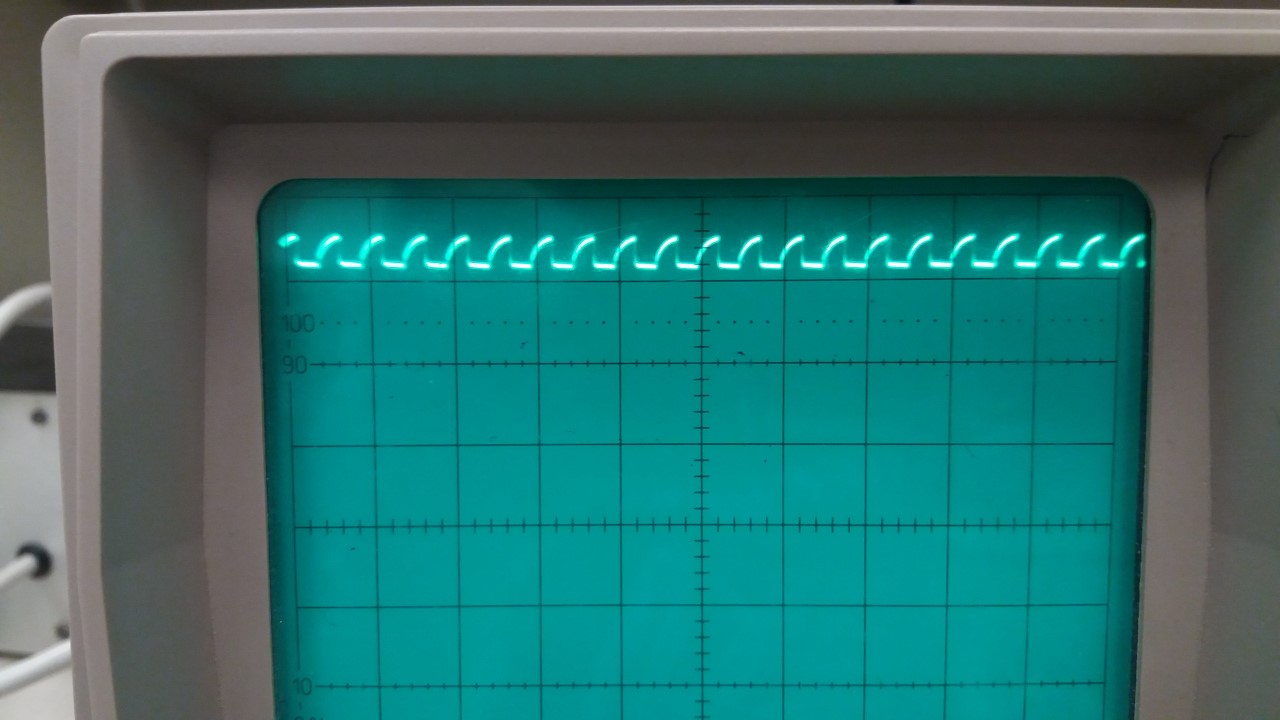
I think you should forget 10 K resistors, and use 5K. This isn't causing your voltage problem on the Low side, but it appears to me your scope is showing way too much latency on the rise time. Way too much. This is probably going to affect timing, and 5K will allow a faster rise time. The datasheet shows 10K on the Si7017 typical application, but 5K should be ok.
Third thing is you have to isolate your low voltage problem. One strategy for doing that would be to disconnect the TMP112 and Si7021 devices, but leave your pullup resistors in place. then, put a scope on your clock and data lines, and have the Uno scan the bus. You might see the expected voltages. If not, you might make sure you are using the scope right, e.g., are you using 10x probes with the the corresponding setting on your scope?
if you get the correct voltage in the configuration with only an Uno, add things in one at a time until you see which one is providing the DC offset.
Lastly, you might want to add .01 mf caps on your circuit near the voltage and ground of the TMP112 and Si7021. These will eliminate switching noise cause by the internals of the respective chips. Above 400Khz, these are almost required, but at lower speeds, probably not. If you add them, place them as close as possible to the power and ground on the chips, keeping lines as short as possible.
Good luck, I'll check back later.