@mhm-k The alternative is to use a 3.3V Arduino microcontroller.
You are right, but I am using 3.3v power supply for the I2C multiplexer and sensors.
Arduino mega also has 3.3V output on board.
does this still need a level shifter? I assume 3.3v to feed the sensor and the multiplexer, and 3.3v signal on the way back should not cause problems, does it?
@mhm-k Yes it does matter, because you can't power the TCA9548A multiplexer with 3.3V and then drive its inputs with 5V SCL and SDA signals from the Mega.
In the datasheet of multiplexer is mentioned that it comes with voltage translator,
"Allows voltage-level translation between 1.8-V, 2.5-V, 3.3-V, and 5-V buses". This the exact sentence from the datasheet.
Do I steel need level shifter? And if I do, is it possible to use only one shifter between TCA and Arduino board?
Hi,
Please don't do that, it makes the flow of the thread very confusing.
Each time you want to add something new, please do it in a new post.
Do you have an airtight seal around the 280?
If you put some pressure or vacuum in the pipe, does it hold when you seal it off?
Tom... ![]()
![]()
![]()
![]()
The TCA9548A can do the level shifting if you power it with 3.3V as I wrote before.
Can you give a link to your TCA9548A module ?
Your link to Aliexpress can be shortened to this: https://nl.aliexpress.com/item/32773684231.html
But that link is useless for me. There are two modules, one with a voltage regulator and one without. The voltage regulator has a voltage drop (0.1V to 1V depending on the voltage regulator), so if you power that with 3.3V, then the sensor gets less voltage.
The 'bmp' object stores data in it for that sensor. You need a 'bmp' for each individual sensor.
You have to seperate the GND wire for sensors from the GND wires of power things, such as the valves. Use a GND from the Arduino board together with SDA and SCL (and 3.3V or 5V) for the sensors and don't connect anything else to that GND wire.
I hope that I made it clear that you have to take a few steps back, you can not fix this quickly, you have to do your project in the right way.
Hi,
Looking at the 9548 breakout, it doesn't seem to have built in pullups for the I2C lines to the 280s.
If the 280 has them on board, they are only 10K which my be to high a value for your lead lengths.

Tom... ![]()
![]()
![]()
![]()
Okay, won't happen again ![]()
Yes it is air tight. when the electric valves are closed, there is no leak. completely isolated from the outside.
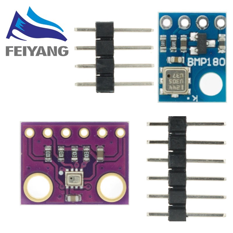
This is the module I am using:
TCA9548A
The link from Ali express contains two modules, one of them is bmp280 and the other is bmp180, I have the first one (purple).
electric valves are using different GND. All of them are connected to the same sealed-acid battery and a charger. But I have separate voltage regulators for valves in groups of three. Arduino and sensors have their own voltage regulators.
I don't really care about being quick. and am taking steps back to understand where I made a mistake. I actually am here because of that.
@mhm-k I was wrong. Since the I2C outputs are open-drain and require pull-up resistors, it should be possible to power the TCA9548A at 5V, provided the breakout boards are powered with 3.3V.
Hi,
Have you got some simple code that just reads the 280s and nothing else.
Leave out the keypad and SD, even the LCD .
Put the readings on the IDE serial monitor.
Lets test your base 280 hardware with the simplest of code to see the integrity of the wiring and setup.
Tom... ![]()
![]()
![]()
![]()
Hello again Tom;
I did it and I wrote the code as simple as it's possible!
I get very reasonable data on the serial! ![]()
here is the code:
// Include Wire Library for I2C
#include <Wire.h>
#include <SPI.h>
#include <Adafruit_BMP280.h>
#include <Adafruit_Sensor.h>

// Create an object for each
Adafruit_BMP280 bmp0;
Adafruit_BMP280 bmp1;
Adafruit_BMP280 bmp2;
Adafruit_BMP280 bmp3;
Adafruit_BMP280 bmp4;
Adafruit_BMP280 bmp5;
Adafruit_BMP280 bmp6;
Adafruit_BMP280 bmp7;

void TCA9548A(uint8_t bus)
{
  Wire.beginTransmission(0x70);  // TCA9548A address is 0x70
  Wire.write(1 << bus);          // send byte to select bus
  Wire.endTransmission();
}


void setup() {
  // Start Wire library for I2C
  Wire.begin();
  Serial.begin(9600);
  // Initialize BMP
  bmp0.begin();
  bmp1.begin();
  bmp2.begin();
  bmp3.begin();
  bmp4.begin();
  bmp5.begin();
  bmp6.begin();
  bmp7.begin();
}


void loop() {
 TCA9548A(0);
 bmp0.begin();
   bmp0.readPressure();
   Serial.print(" 0 = ");
   Serial.println( bmp0.readPressure());

   TCA9548A(1);
 bmp1.begin();
   bmp1.readPressure();
 Serial.print(" 1 = ");
 Serial.println( bmp1.readPressure());

    TCA9548A(2);
 bmp2.begin();
   bmp2.readPressure();
 Serial.print(" 2 = ");
 Serial.println( bmp2.readPressure());

    TCA9548A(3);
 bmp3.begin();
   bmp3.readPressure();
 Serial.print(" 3 = ");
 Serial.println( bmp3.readPressure());

    TCA9548A(4);
 bmp4.begin();
   bmp4.readPressure();
 Serial.print(" 4 = ");
 Serial.println( bmp4.readPressure());

    TCA9548A(5);
 bmp5.begin();
   bmp5.readPressure();
 Serial.print(" 5 = ");
 Serial.println( bmp5.readPressure());

    TCA9548A(6);
 bmp6.begin();
   bmp6.readPressure();
 Serial.print(" 6 = ");
 Serial.println( bmp6.readPressure());

    TCA9548A(7);
 bmp7.begin();
   bmp7.readPressure();
 Serial.print(" 7 = ");
 Serial.println( bmp7.readPressure());
 Serial.println(" ");
   delay(1000);

}
Here is the results on channel 0 to 7;

That's better ![]() It is a good start.
It is a good start.
If you request the temperature, and if you warm them up one by one, does the right sensor show an increased temperature ?
The I2C multiplexer module is good. It is a copy of Adafruit: https://www.adafruit.com/product/2717. Adafruit provides a schematic.
You can enable the 10k pullup on the Arduino side or not, both is okay. The Arduino Mega 2560 has already 10k pullup resistors.
The purple BMP280 module is good. It has 10k pullup resistors, so all your I2C buses have pullup resistors.
Are all the BMP280 modules and the multiplexer powered with 3.3V ? That's very good.
The sketch looks a lot cleaner ![]() Can you put all the 'bmp1' to 'bmp7' into an array ? If you do, be sure that the constructors are called.
Can you put all the 'bmp1' to 'bmp7' into an array ? If you do, be sure that the constructors are called.
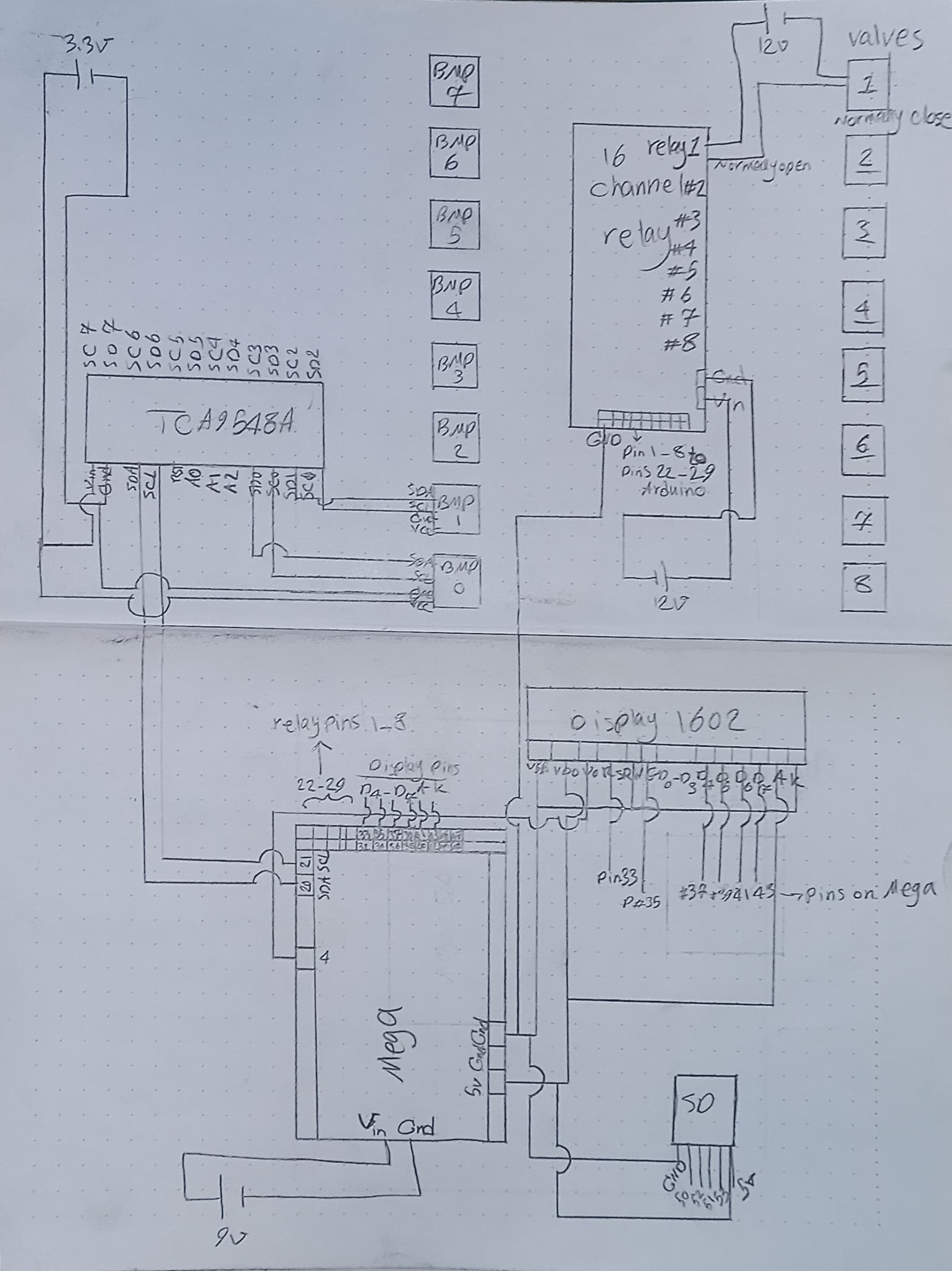
Could you show a schematic with the wiring ? If you draw it on a piece of paper with a pen and make a photo of it, that would be very helpful.
Thanks Koepel,
I added Temperature readings to the code. Then I blew hot air with a hair dryer inside each tube and yes the temperature goes up for that specific sensor.
I'll do the array too.
what would be the next step?
Powering the I2C multiplexer and the sensors with 3.3V from the Mega.
The most important wire is missing ! That is the GND wire from the Mega to the I2C multiplexer. I would like that see that along the SDA and SCL.
The 12V circuit for the valves is not connected to the Arduino circuit, that is good. Does the relay module have opto-couplers and are they 12V relays ? So the 12V power for the relays is also not connected to the Arduino circuit ? Nice.
The LCD backlight and the 8 opto-couplers to the relays require some current. You could power the Mega with 7.5V to the power barrel jack or to VIN. Is that now a 9V adapter ? that's fine. Sometimes it is possible to power an Arduino board with 5V.
The next thing is to throw sparks and electric pulses and all kind of nasty things around and trying to melt metal contacts ![]() I mean using the relays with the valves. You might need a RC snubber circuit over the relay contacts. Can you replace the relays with solid state drivers ?
I mean using the relays with the valves. You might need a RC snubber circuit over the relay contacts. Can you replace the relays with solid state drivers ?
I assume you don't know that a TCA9548A is also a level shifter.
The PCA9548A should however be powered with 5volt, because it has to deal with 5volt I2C from the Mega.
Leo..
No ! Please don't do that.
The VCC limits the maximum voltage that is passed through. Read the datasheet: "The pass-gate transistors of the TCA9548A are constructed such that the VCC voltage can be used to limit the maximum voltage that is passed from one I2C bus to another".
The voltage on the primary I2C-bus and on all the sub-I2C-busses is created with pullup resistors. To avoid that the 5V from the primary side is passed on, the VCC limits the maximum voltage that is passed on and should be 3.3V. Since all the I2C pins are 5V tolerant, that is used for level translation. With this construction, a 3.3V from a sub-I2C-bus translates still to a 5V I2C-bus on the primary side (with VCC at 3.3V).
This is the same for the TCA9548A and the older PCA9548A.
Is it not okay to power multiplexer and sensors with an external power source?
Okay, I will connect the Gnd of the multiplexer to the mega.
The 12v supply for the relay is isolated from Arduino, also the relay board has opto-coupler and relays are 12v too, so not only they won't be bothered by 12v supply, but they must be fed a 12v source or they won't work! I tried that before ![]()
Don't know about the RC snubber. I think I'm good with the relay and no need for solid state drives, as no high voltage or current is engaged and the costs are also lower. By experience and reading I found 9v suitable for Mega, opto-couplera have their own power supply, LCD back light has the pin 4 and set the output of 100 to light it up! No potentiometer needed.
Don't worry about melting anything, because the max current passing through a relay is about 500 mAh and a valve or relay won't be low more than 50-100 Mili seconds. There won't be any heat causing the melting.
I'll consider all these, but the thing is I don't see the relay and valves have anything to do with the wrong reading, actually they are almost logically not related to sensors and Mega. They just do what they are told to do, and actually they do it right, they are the best performers of the show ![]()
![]()