I'm not familiar with the use of the ESP32-S2 serial com ports
My bad, Jim- Just had a look, I do have a Metro M0 Express as well. ( Adafruit METRO M0 Express - designed for CircuitPython (ATSAMD21G18) | The Pi Hut). I did recall seeing one but yeah, sorry about that.
So which board do you plan on using?
I can use any- I think Metro M0 would probably be most suited after reading about it. But I'm open to suggestions.
For the metro M0:
In your original code of post #1 add the following to setup()
Serial1.begin(9600, SERIAL_8E1)
Then change:
node.begin(1, Serial);
to
node.begin(1, Serial1);
Thats all.
This method wouldn't require SoftwareSerial?
No.
Thanks for all the help, Jim.
I'm still getting an error- Error Code E0 (or E2 if I switch the tx and rx).
This is what my circuit roughly looks like -

**Correction, +5V to Vcc, not VIn
I had a look through someone else's forum with a pretty similar error - Error in Modbus RTU communication using Arduino Uno - Using Arduino / Networking, Protocols, and Devices - Arduino Forum
But it was of no avail. I'm at lost at what might be causing this error. I tried putting a resistor between a and b as well. Still error.
The connections are correct and you do need the 120 ohm resistor.
However I'm not sure if the regiser numbers are correct
I think you need to read 2 registers since the result is a 32 bit float.
Change
result = node.readInputRegisters(data_register[i], 1);
to
result = node.readInputRegisters(data_register[i], 2);
I believe that the Adafruit Metro M0 is a 3.3v device. Your MAX485 is a 5V device. That means that your RO signal going into the M0 will exceed the 3.3V level of the SAMD21 - I assume the SAMD21 isn't 5V tolerant - but it might be. There is a MAX3485 chip designed for 3.3V systems.
Looking way back at your code in post #1, do you still have this bit of code exactly as you provided?
void postTransmission()
{
  digitalWrite(MAX485_RE_NEG, LOW);
  digitalWrite(MAX485_DE, LOW);
  delay(500);
}
If so, you need to remove the delay() as that will really mess up your Modbus comms and will most likely result in the E2 error message you had.
In order to read a 32-bit number, you need to read 2 consecutive 16-bit registers as @jim-p showed you.
Thanks Jim, Mark. I've tried using a voltage level shifter as well- I'll give it another attempt with the changes in the code.
It might be worth posting your latest code here just to refresh our memories!!
Still getting Error code E2.
Here's my code:
#include <ModbusMaster.h>

// pin names
#define ledPin 13
#define MAX485_DE 5
#define MAX485_RE_NEG 5
#define MODBUS_RX_PIN 0
#define MODBUS_TX_PIN 1

#define MODBUS_SERIAL_BAUD 9600

uint16_t data_register[3] = {0x0BD4, 0x0BB8, 0x0BEE}; //Voltage, current and powe

ModbusMaster node;

void preTransmission()
{
  delay(500);
  digitalWrite(MAX485_RE_NEG, HIGH);
  digitalWrite(MAX485_DE, HIGH);
}

void postTransmission()
{
  digitalWrite(MAX485_RE_NEG, LOW);
  digitalWrite(MAX485_DE, LOW);
}


void setup()
{
  Serial.println("Start ");
  pinMode(ledPin,OUTPUT);

  pinMode(MAX485_RE_NEG, OUTPUT);
  pinMode(MAX485_DE, OUTPUT);

  digitalWrite(MAX485_RE_NEG, LOW);
  digitalWrite(MAX485_DE, LOW);

  Serial.begin(9600);
  Serial1.begin(9600, SERIAL_8E1);

  // Modbus Slave ID1
  node.begin(1, Serial1);

  node.preTransmission(preTransmission);
  node.postTransmission(postTransmission);
}

bool state = true;

void loop()
{
  uint8_t result;
  uint16_t data[2];

  // result = node.readHoldingRegisters(0x001E, state);
  // state = !state;

  // result = node.readInputRegisters(0x0031, 16);
  // if (result == node.ku8MBSuccess)
  // {
  //   Serial.print("Meter name: ");
  //   Serial.println(node.getResponseBuffer(0x04)/100.0f);
  // }

    int i;
    float reading;
        for(i=0; i<=2; i++){
            result = node.readInputRegisters(data_register[i], 2);

        if (result == node.ku8MBSuccess) {
          Serial.println("Success, Received data: ");

           data[0]=node.getResponseBuffer(0x00);
           data[1]=node.getResponseBuffer(0x01);

           //read voltage
           if(data_register[i] == 0x0BD4){
            Serial.print("Voltage: ");
            reading = *((float *)data);
            Serial.print(reading);
            Serial.println(" Volts");
           }
           //read current
           if(data_register[i] == 0x0BB8){
            Serial.print("Current: ");
            reading = *((float *)data);
            Serial.print(reading);
            Serial.println(" Amps");
           }
           //read power
           if(data_register[i] == 0x0BEE){
            Serial.print("Frequency: ");
            reading = *((float *)data);
            Serial.print(reading);
            Serial.println(" kW");
           }
        } else {
          Serial.print("Failed, Response Code: ");
          Serial.print(result, HEX);
          Serial.println("");
          delay(5000);
        }

    }

  digitalWrite(ledPin,HIGH);//turn the LED on
  delay(1000);               //wait
  digitalWrite(ledPin,LOW); //turn the LED off
  delay(1000);               //wait

//   delay(10000);
}
Here's my rough circuit:

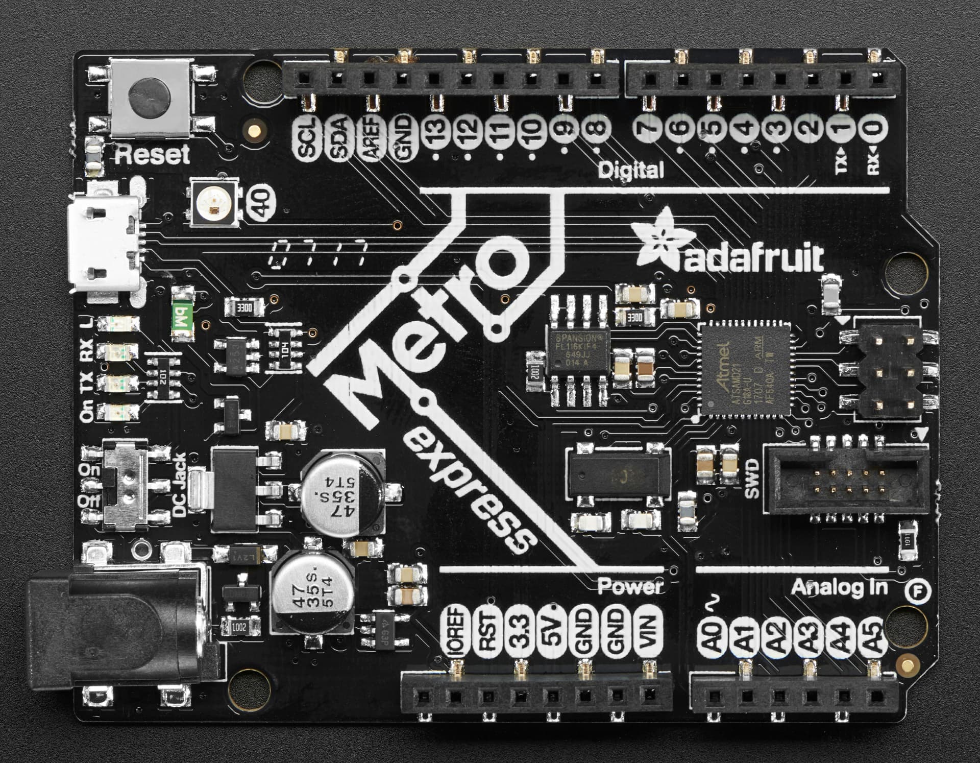
Ok, so just to be clear here, is this the board you are using:
You should also remove the delay from the preTransmission function as well.
I couldn't see from the web page docs you linked to back in post #6 what function code you are supposed to use to retrieve data from the meter - that's determined by whether you use readInputRegisters() or readHoldingRegisters().
It may be worth trying both to see which one gets you a response without an error code.
And if that wasn't enough to sort out, then you have the task of sorting out the register address you want to read from. You will note from the Meter Data - Current, Voltage & power page, that the table shows an address and a register.
For Voltage, the address is given as 0x0BD4 and the register as 3029. You may also have noticed that 0x0BD4 (hex) does not equal 3029 (decimal) - it's out by 1. That always catches me out and it's a pain in the backside.
I would try to query address 0x0BD5 (or even 0x0BD3 as I can't remember whether to add 1 or subtract 1!) using calls to both readInputRegisters() or readHoldingRegisters() with a count of 2.
That is my board, yes.
It was a link to the user guide of the energy meter I'm using - A9MEM2050 - modular single phase power meter iEM2050 - 230V - 45A with comm Modbus | Schneider Electric UK
I believe this is the important bit from there -

I'll give the variations a go, thank you.
Hi, you dont need level translator, Ive made it with just ESP32 and MAX485.
Hi @ezrax123 , did you manage to solve the problem?