Internal pull up resistor in i2c, Arduino uno

As I understand the history, the original intent was chip-to-chip comms; thus, internal or external pullups were possible depending on the semiconductor design.

What is desired is to match the characteristic impedance of sender, transmission line, and input device to minimize impedance mismatches and provide optimum signal transmission and minimum reflection.

Hughes_TechnicalArticles_BetterPCBDesign_Fourier

As the above figures show, a real digital signal has a large bandwidth and any portion of that energy might create a resonance in your circuit. This is in contrast to RF signals that have very narrow bandwidth with easy to calculate resonances.

If you do manage to create standing waves, you will create enormous sources of noise that can overwhelm any signal line in the vicinity.

1 Like

They are but the original specification did put a limit of 2mA maximum pull down current. Most internal pullup resistors are way short of being able to supply the standard 1mA required. Yes I know all about reflections and standing waves but this is not an issue with I2C communications. What is the big issue and the one that limits the speed of operations is rise and fall time of the edges. This is manly governed by the capacitance seen by the signal wires. If you have ever looked at the I2C signal from an Arduino on an oscilloscope with just the pull up resistors you will instantly see how crappy (technical term used by engineers) the signal is. But at the [ irony ] great expense [/ irony ] of two resistors it can be made to look pristine, and will actually work better. See Effects of Varying Pullup Resistors.pdf

Nice animated gif of the Fourier synthesis of a square wave but I am not sure on the relevance to the question in hand. Because if it were only a matter of pure bandwidth then the I2C signals would not have asymmetric rise and fall times.

Ah, a fair observation.

Electrical signals of any type convey the maximum power (thus 'cleanest' waveform) when viewed in the context of what EE's know as the Maximum Power Transfer Theorem

My (not so well made) point is that the best signal waveform is when the best impedance match occurs. As you noted, we are working with 1mA to 2mA sink current max, so our resistance minimums are set by the implementation specification: driving up to 400pF of capacitive load. The inductive components are discussed in the article I linked.

I did enjoy the paper you linked on the oscilloscope traces. Added to my stash of PDFs.

Thanks, it is nice when an Arduino topic spills over into the underlying EE and physics topics - especially with solid lab work to backup the discussion.

Ray

1 Like

Hi ZX
Where was is written that Max30101 includes the pull up resistor in the i2c lines?

Below its recommended to connect externally pull up resistors to i2c

Whoops ... INT pin is minimum 4.7KΩ
image

If you read my post, you will see that I was talking about the Sparkfun module.


https://learn.sparkfun.com/tutorials/sparkfun-photodetector-max30101-hookup-guide/all

Thanks :slightly_smiling_face:
I shall connect 2.2k pull ups between the max30101 and arduino uno on the i2c lines, right?

For many analog signals and mearly all digital signals low impedance sources drive high impedance loads (if using voltage to represent a signal and want fanout greater than 1). Fanout means the same signal can go to more than one destination without being distorted/attenuated.

You are thinking of transmission lines, I2C is very definitely not a transmission line bus - its definitely modeled as capacitive (which is why the bandwidth is low compared to impedance-matched busses like ethernet/USB/etc). LVDS signalling for instance which is also impedance matched often handles close to 1Gbaud, nearly 4 orders of magnitude faster.

Mark,
You are correct.

I was old when I2C was invented (or designed or realized by Philips.) My EE studies was classical (as in old like classical music) and I am certain that my secondary concentrations in chemistry and physics distracted from the electrical engineering aspects. My elective in thermodynamics likely toasted many brain neurons. I was employed in my concentration for only a year and that was in research which everyone knows is not real-world anything.

The above being a truth, I have forgotten much. But, I do seem to believe that any electronic problem involves reducing it to one or more fundamental "Laws": Ohm's, Joule's, Kirchhoff's, etc.

A ED article (a sales attempt to justify expensive function signal generator) states in summary:

...the actual output waveform’s amplitude changes based on different load impedance under low-frequency conditions. But as frequency increases, the system circuit models become more complex. In this case, it may be necessary to regard the cable as a transmission line and consider reflection and complex load (not only resistance, but also inductance or/and capacitance). Under certain mismatching conditions, the amplitude and shape of a waveform produced by an AFG can end up being significantly different from the ideal source output. These conditions are usually caused by mismatched load impedance or the use of mismatched long cables. The impact of bad reference waveforms can be significant, including measurement errors that lead to inaccurate conclusions and, under extreme conditions, damage to the DUT.

I read that some researchers have resorted to using Joule's Law to explain electron tunneling in semiconductors... as I (think) I remember, Joule's Law is just a restatement of Ohm's Law which is a restatement of Watt's Law ... I can no longer remember the chronology!

People often ask; what is the difference between Watt’s law and Ohm’s law? While Ohm’s law defines the relationship between resistance, voltage, and current in a circuit; Watt’s law defines the relationship between power, voltage and current. However, you can combine these laws to get useful formulas. According to Ohm’s law, I=V/R and V=IR. Substituting these into Watt’s formula, we get:

P=Ix IR=I2R and P=VxV/R=V2/R

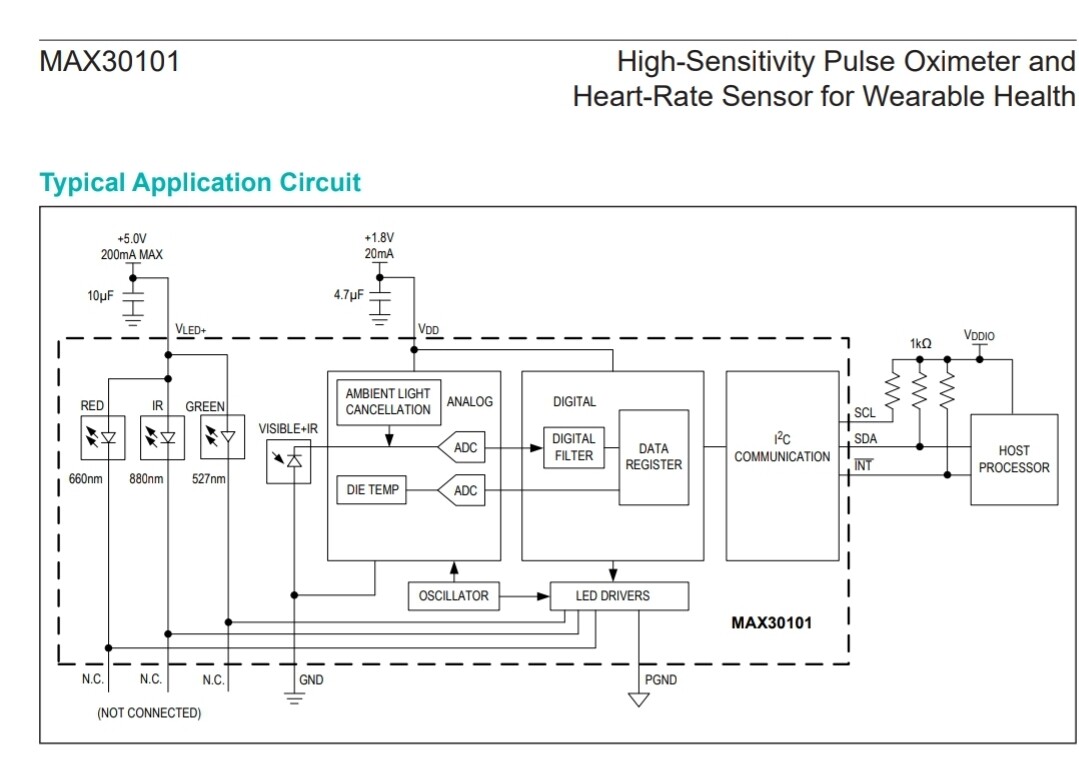
I agree that the I2C bus is not a transmission line as Hams radio operators or even AC electrical engineers would recognize; still if I drop back to those old Laws, it makes more sense to me: match everything up, honor the bus specification, minimize power loss and the signal transmission will be better.

Best,

Ray

This topic was automatically closed 180 days after the last reply. New replies are no longer allowed.