I assume the other inputs are open. Noise can make them go 0 or 1 at random. They will not trigger the ISR, as only the lower 4 are set for PCINT, and they are not used in the ISR.
But they show up in your print, try: Serial.print(previousInputs & 0x0F, BIN)
to get rid of them.
Be aware that leading zeroes in the print output are ignored.
Better, to get a nice table:
if (bitRead(previousInputs, 3)) Serial.print(“1”);
else Serial.print(“0”);
if (bitRead(previousInputs, 2)) Serial.print(“1”);
else Serial.print(“0”);
if (bitRead(previousInputs, 1)) Serial.print(“1”);
else Serial.print(“0”);
if (bitRead(previousInputs, 0)) Serial.print(“1”);
else Serial.print(“0”);
Serial.println(“”);
What puzzles me is that the ISR is triggered a number of times without showing a change. This is as strange as all 4 inputs changing at the same time.
Please post the sketch you actually use.
//         SKETCH TO TEST COMMANDS FROM FLYSKY FS-i6X RADIO CONTROL
//@@@@@@@@@@@@@@@@@@@@@@@@@@@@@@@@@@@@@@@@@@@@@@@@@@@@@@@@@@@@@@@@@@@@@@@@@@@@@@@@@@@@@@@@@@@@@@@@@@@@@@@@@@@@@@@@@@@@@@@@@@@@@@@@
//                  WARNING: PROGRAM PROVIDED AS IS, NO WARRANTY
//@@@@@@@@@@@@@@@@@@@@@@@@@@@@@@@@@@@@@@@@@@@@@@@@@@@@@@@@@@@@@@@@@@@@@@@@@@@@@@@@@@@@@@@@@@@@@@@@@@@@@@@@@@@@@@@@@@@@@@@@@@@@@@@@
//
//@@@@@@@@@@@@@@@@@@@@@@@@@@@@@@@@@@@@@@@@@@@@@@@@@@@@@@@@@@@@@@@@@@@@@@@@@@@@@@@@@@@@@@@@@@@@@@@@@@@@@@@@@@@@@@@@@@@@@@@@@@@@@@@@
//         Define variables for channel numbers
//@@@@@@@@@@@@@@@@@@@@@@@@@@@@@@@@@@@@@@@@@@@@@@@@@@@@@@@@@@@@@@@@@@@@@@@@@@@@@@@@@@@@@@@@@@@@@@@@@@@@@@@@@@@@@@@@@@@@@@@@@@@@@@@@
#define CHA1 0    // CHA1 equals 0 (Channel 1 controls ROLL)
#define CHA2 1    // CHA2 equals 1 (Channel 2 controls PITCH)
#define CHA3 2    // CHA3 equals 2 (Channel 3 controls GAS/THROTTLE)
#define CHA4 3    // CHA4 equals 3 (Channel 4 controls YAW)
/* To read signals from RC receiver with Arduino UNO R3
  CH1 is connected to Arduino pin 8 (PB0)
  CH2 is connected to Arduino pin 9 (PB1)
  CH3 is connected to Arduino pin 10 (PB2)
  CH4 is connected to Arduino pin 11 (PB3)
*/
volatile unsigned int pwmLength[4]; // PWM pulse durations on the receiver channels
volatile unsigned int interruptTime; // Time used in interrupt service routine (ISR) to identify beginning of ANY interrupt.
                                     // This is the time when we enter the ISR routine ANY time an interrupt is triggered.
volatile unsigned int pwmSignalStart[4]; // Array of start times of PWM signals at each of the receiver channels
volatile byte chaPreviousState[4]; // Array of states (HIGH or LOW) of each of the reception channels BEFORE an interrupt occurs.
                                   // Pin Levels in a digital pin can be HIGH or LOW. When reading or writing to a digital pin
                                   // there are only two possible values a pin can be-set-to: HIGH and LOW. These are the same
                                   // as true and false, as well as 1 and 0.
volatile unsigned int ch1duration;  // calculating indexes for arrays takes a lot of time
volatile unsigned int ch2duration;
volatile unsigned int ch3duration;
volatile unsigned int ch4duration;
//@@@@@@@@@@@@@@@@@@@@@@@@@@@@@@@@@@@@@@@@@@@@@@@@@@@@@@@@@@@@@@@@@@@@@@@@@@@@@@@@@@@@@@@@@@@@@@@@@@@@@@@@@@@@@@@@@@@@@@@@@@@@@@@@
// Declaration of the prototypes of the functions used in the program. When using the Arduino IDE, this declaration is not
// strictly necessary becasuse the IDE does this declaration for you. However, it's a good progamming practice (GPM) to follow.
//@@@@@@@@@@@@@@@@@@@@@@@@@@@@@@@@@@@@@@@@@@@@@@@@@@@@@@@@@@@@@@@@@@@@@@@@@@@@@@@@@@@@@@@@@@@@@@@@@@@@@@@@@@@@@@@@@@@@@@@@@@@@@@@@
void selectInterruptSources(); // function to configure the pins that trigger an interrupt
void showFlyskyPwmLength();  // function to displays in Serial Monitor durations of the PWM signals received via the RC receiver.
//@@@@@@@@@@@@@@@@@@@@@@@@@@@@@@@@@@@@@@@@@@@@@@@@@@@@@@@@@@@@@@@@@@@@@@@@@@@@@@@@@@@@@@@@@@@@@@@@@@@@@@@@@@@@@@@@@@@@@@@@@@@@@@@@
//                  SETUP()
//@@@@@@@@@@@@@@@@@@@@@@@@@@@@@@@@@@@@@@@@@@@@@@@@@@@@@@@@@@@@@@@@@@@@@@@@@@@@@@@@@@@@@@@@@@@@@@@@@@@@@@@@@@@@@@@@@@@@@@@@@@@@@@@@
void setup(){
// Set data rate in bits per second (baud) for serial data transmission. For communicating with Serial Monitor (SM),
// make sure to use one of the baud rates listed in the menu at the bottom right corner of the SM screen.
  Serial.begin(600,SERIAL_8N1);
// Selection of pins used as interrupt sources
  selectInterruptSources();
}

//@@@@@@@@@@@@@@@@@@@@@@@@@@@@@@@@@@@@@@@@@@@@@@@@@@@@@@@@@@@@@@@@@@@@@@@@@@@@@@@@@@@@@@@@@@@@@@@@@@@@@@@@@@@@@@@@@@@@@@@@@@@@@@@@
//                   LOOP()
//@@@@@@@@@@@@@@@@@@@@@@@@@@@@@@@@@@@@@@@@@@@@@@@@@@@@@@@@@@@@@@@@@@@@@@@@@@@@@@@@@@@@@@@@@@@@@@@@@@@@@@@@@@@@@@@@@@@@@@@@@@@@@@@@
void loop(){
  delay(250);
  showFlyskyPwmLength();
}

//@@@@@@@@@@@@@@@@@@@@@@@@@@@@@@@@@@@@@@@@@@@@@@@@@@@@@@@@@@@@@@@@@@@@@@@@@@@@@@@@@@@@@@@@@@@@@@@@@@@@@@@@@@@@@@@@@@@@@@@@@@@@@@@@
//  This function manipulates registers PCICR and PCMSK0 so as to allow digital pins/terminals to trigger interrupts
//@@@@@@@@@@@@@@@@@@@@@@@@@@@@@@@@@@@@@@@@@@@@@@@@@@@@@@@@@@@@@@@@@@@@@@@@@@@@@@@@@@@@@@@@@@@@@@@@@@@@@@@@@@@@@@@@@@@@@@@@@@@@@@@@
void selectInterruptSources(){

		PCICR  |= (1 << PCIE0);
    PCMSK0 |= (1 << PCINT0); // Variable PCINT0 in iom328p.h is defined as equal to 0.
    PCMSK0 |= (1 << PCINT1); // Variable PCINT1 in iom328p.h is defined as equal to 1.
    PCMSK0 |= (1 << PCINT2);  // Variable PCINT2 in iom328p.h is defined as equal to 2.
    PCMSK0 |= (1 << PCINT3);  // Variable PCINT3 in iom328p.h is defined as equal to 3.
}
/* To read signals from RC receiver with Arduino UNO R3
CH1 is connected to Arduino pin 8 (PB0)
CH2 is connected to Arduino pin 9 (PB1)
CH3 is connected to Arduino pin 10 (PB2)
CH4 is connected to Arduino pin 11 (PB3)*/

ISR(PCINT0_vect) {
//  "ISR(PCINT0_vect)" is the Interrupt Service Routine for pins of PORT B, with PCINT0_vect being a runtime parameter
//  corresponding to the source of the interrupt (PORT B). It executes intructions from PCINT0..PCINT7 on MCU. These map to
//  pins/terminals D8..D13 on the Arduino UNO R3 board, the two high bits (6 & 7) map to the crystal pins and are not usable.
  unsigned long presentTime = micros();
  byte presentInputs = PINB; // PINB reads input status of ALL pins of Port B Register
  static byte previousInputs = 0;  // static variables, initialized outside ISR
  static unsigned long ch1up = 0;
  static unsigned long ch2up = 0;
  static unsigned long ch3up = 0;
  static unsigned long ch4up = 0;
  byte edgesUp = presentInputs & ~previousInputs;
  if (bitRead(edgesUp, 0)) ch1up = presentTime;
  if (bitRead(edgesUp, 1)) ch2up = presentTime;
  if (bitRead(edgesUp, 2)) ch3up = presentTime;
  if (bitRead(edgesUp, 3)) ch4up = presentTime;
  byte edgesDown = ~presentInputs & previousInputs;
  if (bitRead(edgesDown, 0)) ch1duration = presentTime - ch1up;
  if (bitRead(edgesDown, 1)) ch2duration = presentTime - ch2up;
  if (bitRead(edgesDown, 2)) ch3duration = presentTime - ch3up;
  if (bitRead(edgesDown, 3)) ch4duration = presentTime - ch4up;
  Serial.print("previousInputs before: ");
  Serial.print(previousInputs, BIN);
  Serial.print(" after: ");
  previousInputs = presentInputs;
  Serial.println(previousInputs & 0x0F, BIN);
  // Serial.println(previousInputs, BIN);
  // delay(50000); // Does NOT work inside the ISR. While you are in an ISR, the interrupt that advances micros() can't trigger,
                   // so the delay() routine, which depends on micros(), won't be able to work properly.
}
//@@@@@@@@@@@@@@@@@@@@@@@@@@@@@@@@@@@@@@@@@@@@@@@@@@@@@@@@@@@@@@@@@@@@@@@@@@@@@@@@@@@@@@@@@@@@@@@@@@@@@@@@@@@@@@@@@@@@@@@@@@@@@@@@
//  Prints to serial monitor the pulse durations/lengths received from channels 8, 9, 10, 11 via the radio receiver
//@@@@@@@@@@@@@@@@@@@@@@@@@@@@@@@@@@@@@@@@@@@@@@@@@@@@@@@@@@@@@@@@@@@@@@@@@@@@@@@@@@@@@@@@@@@@@@@@@@@@@@@@@@@@@@@@@@@@@@@@@@@@@@@@
void showFlyskyPwmLength() {
  Serial.print("Roll PWM Length: ");
  Serial.print(ch1duration);
  Serial.print("\u00B5s"); // Unicode code point \u00B5 for micro plus letter "s"

  Serial.print(" -> Pitch PWM Length: ");
  Serial.print(ch2duration);
  Serial.print("\u00B5s"); // Unicode code point \u00B5 for micro plus letter "s"

  Serial.print(" -> Gas PWM Length: ");
  Serial.print(ch3duration);
  Serial.print("\u00B5s"); // Unicode code point \u00B5 for micro plus letter "s"

  Serial.print(" -> Yaw PWM Length: ");
  Serial.print(ch4duration);
  Serial.print("\u00B5s"); // Unicode code point \u00B5 for micro plus letter "s"
  Serial.println("");
}
I noticed that your baudrate is ridiculously low. It is possible, though not recommended, to use Serial.print in an ISR. It is not recommended because once the outputbuffer is full, the serial communication is blocking. The outputbuffer is 64 characters long. After sending 1 character only 1 character can be added and it’s blocking again for about 16 milliseconds. Compare this with the expected rate of triggering the ISR: 8 times in 20 milliseconds at minimum, when driven by your RC system.
Next problem: the message in loop() is bigger than 64 characters and will immediately affect the triggering of the ISR. At 600 baud this blockage will last more than 1 second, in this time you won’t be able to measure anything.
I suggest to make the line: Roll 1234, Pitch 1357, Gas 1432, Yaw 1987 μs (less than 64 characters) and baudrate 115200 (both in sketch and in IDE).
For the debug line in the ISR: print only 5 characters per call (4 bits and LF/CR).
I used that BAUD rate to slow down the Serial Monitor. Now, I seem to have a bigger problem. All serial prints from showFlyskyPwmLength() are zero. Would it be possible that the receiver (or transmitter??) went busted somehow??
Sketch is now working as well as before, but I do not understand why printing from showFlyskyPwmLength() never occurs when I have Serial.prints() in the ISR. It only prints from showFlyskyPwmLength() when I remove all serial prints from the ISR. It's like it gets stuck inside the ISR, makes no sense to me.
I switched to higher baud and now I can see "some" printing from showFlyskyPwmLength(). However, most the printing is from of the ISR. In addition, the pulse durations are way off the gimbals position. When I remove all printing from the ISR, these errors disappear and the pulse durations are way more accurate.
Much better after implementing your suggestions. What I still can't understand is why there are so many more lines printed inside the ISR than from showFlyskyPwmLength() called in loop.
//@@@@@@@@@@@@@@@@@@@@@@@@@@@@@@@@@@@@@@@@@@@@@@@@@@@@@@@@@@@@@@@@@@@@@@@@@@@@@@@@@@@@@@@@@@@@@@@@@@@@@@@@@@@@@@@@@@@@@@@@@@@@@@@@
//         SKETCH TO TEST COMMANDS FROM FLYSKY FS-i6X RADIO CONTROL
//@@@@@@@@@@@@@@@@@@@@@@@@@@@@@@@@@@@@@@@@@@@@@@@@@@@@@@@@@@@@@@@@@@@@@@@@@@@@@@@@@@@@@@@@@@@@@@@@@@@@@@@@@@@@@@@@@@@@@@@@@@@@@@@@
//         Define variables for channel numbers
//@@@@@@@@@@@@@@@@@@@@@@@@@@@@@@@@@@@@@@@@@@@@@@@@@@@@@@@@@@@@@@@@@@@@@@@@@@@@@@@@@@@@@@@@@@@@@@@@@@@@@@@@@@@@@@@@@@@@@@@@@@@@@@@@
#define CHA1 0    // CHA1 equals 0 (Channel 1 controls ROLL)
#define CHA2 1    // CHA2 equals 1 (Channel 2 controls PITCH)
#define CHA3 2    // CHA3 equals 2 (Channel 3 controls GAS/THROTTLE)
#define CHA4 3    // CHA4 equals 3 (Channel 4 controls YAW)
/* To read signals from RC receiver with Arduino UNO R3
  CH1 is connected to Arduino pin 8 (PB0)
  CH2 is connected to Arduino pin 9 (PB1)
  CH3 is connected to Arduino pin 10 (PB2)
  CH4 is connected to Arduino pin 11 (PB3)
*/
volatile unsigned int pwmLength[4]; // PWM pulse durations on the receiver channels
volatile unsigned int interruptTime; // Time used in interrupt service routine (ISR) to identify beginning of ANY interrupt.
                                     // This is the time when we enter the ISR routine ANY time an interrupt is triggered.
volatile unsigned int pwmSignalStart[4]; // Array of start times of PWM signals at each of the receiver channels
volatile byte chaPreviousState[4]; // Array of states (HIGH or LOW) of each of the reception channels BEFORE an interrupt occurs.
                                   // Pin Levels in a digital pin can be HIGH or LOW. When reading or writing to a digital pin
                                   // there are only two possible values a pin can be-set-to: HIGH and LOW. These are the same
                                   // as true and false, as well as 1 and 0.
volatile unsigned int ch1duration;  // calculating indexes for arrays takes a lot of time
volatile unsigned int ch2duration;
volatile unsigned int ch3duration;
volatile unsigned int ch4duration;
//@@@@@@@@@@@@@@@@@@@@@@@@@@@@@@@@@@@@@@@@@@@@@@@@@@@@@@@@@@@@@@@@@@@@@@@@@@@@@@@@@@@@@@@@@@@@@@@@@@@@@@@@@@@@@@@@@@@@@@@@@@@@@@@@
// Declaration of the prototypes of the functions used in the program. When using the Arduino IDE, this declaration is not
// strictly necessary becasuse the IDE does this declaration for you. However, it's a good progamming practice (GPM) to follow.
//@@@@@@@@@@@@@@@@@@@@@@@@@@@@@@@@@@@@@@@@@@@@@@@@@@@@@@@@@@@@@@@@@@@@@@@@@@@@@@@@@@@@@@@@@@@@@@@@@@@@@@@@@@@@@@@@@@@@@@@@@@@@@@@@
void selectInterruptSources(); // function to configure the pins that trigger an interrupt
void showFlyskyPwmLength();  // function to displays in Serial Monitor durations of the PWM signals received via the RC receiver.
//@@@@@@@@@@@@@@@@@@@@@@@@@@@@@@@@@@@@@@@@@@@@@@@@@@@@@@@@@@@@@@@@@@@@@@@@@@@@@@@@@@@@@@@@@@@@@@@@@@@@@@@@@@@@@@@@@@@@@@@@@@@@@@@@
//                  SETUP()
//@@@@@@@@@@@@@@@@@@@@@@@@@@@@@@@@@@@@@@@@@@@@@@@@@@@@@@@@@@@@@@@@@@@@@@@@@@@@@@@@@@@@@@@@@@@@@@@@@@@@@@@@@@@@@@@@@@@@@@@@@@@@@@@@
void setup(){
// Set data rate in bits per second (baud) for serial data transmission. For communicating with Serial Monitor (SM),
// make sure to use one of the baud rates listed in the menu at the bottom right corner of the SM screen.
  Serial.begin(115200);
// Selection of pins used as interrupt sources
  selectInterruptSources();
}

//@@@@@@@@@@@@@@@@@@@@@@@@@@@@@@@@@@@@@@@@@@@@@@@@@@@@@@@@@@@@@@@@@@@@@@@@@@@@@@@@@@@@@@@@@@@@@@@@@@@@@@@@@@@@@@@@@@@@@@@@@@@@@@@@
//                   LOOP()
//@@@@@@@@@@@@@@@@@@@@@@@@@@@@@@@@@@@@@@@@@@@@@@@@@@@@@@@@@@@@@@@@@@@@@@@@@@@@@@@@@@@@@@@@@@@@@@@@@@@@@@@@@@@@@@@@@@@@@@@@@@@@@@@@
void loop(){
  delay(250);
  showFlyskyPwmLength();
}

//@@@@@@@@@@@@@@@@@@@@@@@@@@@@@@@@@@@@@@@@@@@@@@@@@@@@@@@@@@@@@@@@@@@@@@@@@@@@@@@@@@@@@@@@@@@@@@@@@@@@@@@@@@@@@@@@@@@@@@@@@@@@@@@@
//  This function manipulates registers PCICR and PCMSK0 so as to allow digital pins/terminals to trigger interrupts
//@@@@@@@@@@@@@@@@@@@@@@@@@@@@@@@@@@@@@@@@@@@@@@@@@@@@@@@@@@@@@@@@@@@@@@@@@@@@@@@@@@@@@@@@@@@@@@@@@@@@@@@@@@@@@@@@@@@@@@@@@@@@@@@@
void selectInterruptSources(){

		PCICR  |= (1 << PCIE0);
    PCMSK0 |= (1 << PCINT0); // Variable PCINT0 in iom328p.h is defined as equal to 0.
    PCMSK0 |= (1 << PCINT1); // Variable PCINT1 in iom328p.h is defined as equal to 1.
    PCMSK0 |= (1 << PCINT2);  // Variable PCINT2 in iom328p.h is defined as equal to 2.
    PCMSK0 |= (1 << PCINT3);  // Variable PCINT3 in iom328p.h is defined as equal to 3.
}
/* To read signals from RC receiver with Arduino UNO R3
CH1 is connected to Arduino pin 8 (PB0)
CH2 is connected to Arduino pin 9 (PB1)
CH3 is connected to Arduino pin 10 (PB2)
CH4 is connected to Arduino pin 11 (PB3)*/

ISR(PCINT0_vect) {
  unsigned long presentTime = micros();
  byte presentInputs = PINB; // PINB reads input status of ALL pins of Port B Register
  static byte previousInputs = 0;  // static variables, initialized outside ISR
  static unsigned long ch1up = 0;
  static unsigned long ch2up = 0;
  static unsigned long ch3up = 0;
  static unsigned long ch4up = 0;
  byte edgesUp = presentInputs & ~previousInputs;
  if (bitRead(edgesUp, 0)) ch1up = presentTime;
  if (bitRead(edgesUp, 1)) ch2up = presentTime;
  if (bitRead(edgesUp, 2)) ch3up = presentTime;
  if (bitRead(edgesUp, 3)) ch4up = presentTime;
  byte edgesDown = ~presentInputs & previousInputs;
  if (bitRead(edgesDown, 0)) ch1duration = presentTime - ch1up;
  if (bitRead(edgesDown, 1)) ch2duration = presentTime - ch2up;
  if (bitRead(edgesDown, 2)) ch3duration = presentTime - ch3up;
  if (bitRead(edgesDown, 3)) ch4duration = presentTime - ch4up;

  Serial.print("b: ");
  Serial.print(previousInputs, BIN);
  previousInputs = presentInputs;
  Serial.print(" a: ");
 //  Serial.println(previousInputs & 0x0F, BIN);
  Serial.println(previousInputs, BIN);
}
//@@@@@@@@@@@@@@@@@@@@@@@@@@@@@@@@@@@@@@@@@@@@@@@@@@@@@@@@@@@@@@@@@@@@@@@@@@@@@@@@@@@@@@@@@@@@@@@@@@@@@@@@@@@@@@@@@@@@@@@@@@@@@@@@
//  Prints to serial monitor the pulse durations/lengths received from channels 8, 9, 10, 11 via the radio receiver
//@@@@@@@@@@@@@@@@@@@@@@@@@@@@@@@@@@@@@@@@@@@@@@@@@@@@@@@@@@@@@@@@@@@@@@@@@@@@@@@@@@@@@@@@@@@@@@@@@@@@@@@@@@@@@@@@@@@@@@@@@@@@@@@@
void showFlyskyPwmLength() {
  Serial.print("Roll: ");
  Serial.print(ch1duration);
  Serial.print("\u00B5s"); // Unicode code point \u00B5 for micro plus letter "s"

  Serial.print(" Pitch: ");
  Serial.print(ch2duration);
  Serial.print("\u00B5s"); // Unicode code point \u00B5 for micro plus letter "s"

  Serial.print(" Gas: ");
  Serial.print(ch3duration);
  Serial.print("\u00B5s"); // Unicode code point \u00B5 for micro plus letter "s"

  Serial.print(" Yaw: ");
  Serial.print(ch4duration);
  Serial.print("\u00B5s"); // Unicode code point \u00B5 for micro plus letter "s"
  Serial.println();
}
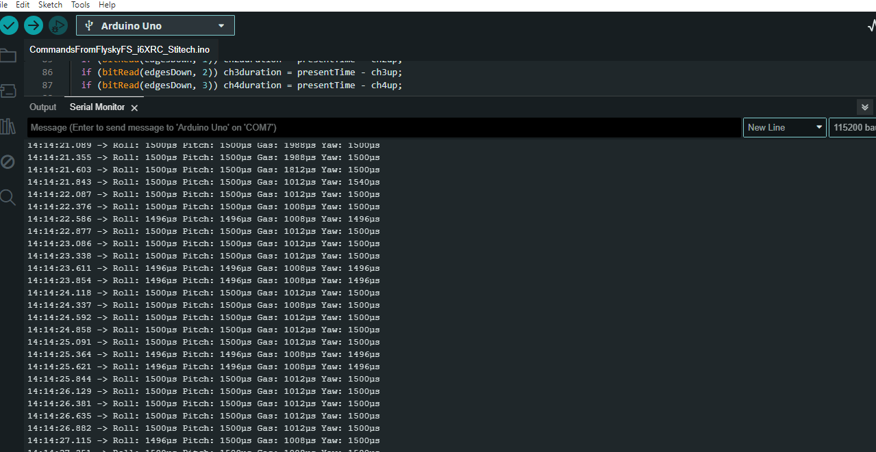
First of all: the timestamps at the left of the screen are added by the Serial Monitor, not by the board.
There are several things that are getting my attention in your screenshot. I counted the triggerings: 3, 5, 5, 4 and 6 times in one millisecond. The times between these groups are: 33, 33, 42, 25 and 33 milliseconds. Sometimes only CH3 changed, sometimes the other 3, sometimes all channels. Each group starts and ends with 0000.
Based on the picture of post #34 I’d expect 5 triggerings with a separation of 1 or 2 milliseconds every 20 milliseconds. Now I think that all channels go high at the same time, CH3 goes down after 1008μs (lowest), the other 3 after 1496μs (neutral), that should give 3 triggerings in a period of 2 milliseconds. I hinted at this possibility in post #37.
At timestamp 1:55:30.793 I see 2 of these groups. Apparently the Serial.print still can’t keep up with all the text it’s supposed to send.
Remove the prints from the ISR and see what happens if you manipulate the gimbals.
Just for confirmation: go back to the sketch in post #1, change the serial speed to 115200 and see what happens.
I guess we spent a long time looking at the wrong places. But we did learn a lot in the mean time.