Explain the algorithm by which you will convert "white noise" into a 1 or 0.
which contains audible range of frequency between 20hz to 20,00 hz
Be aware that by definition, "white noise" contains a uniform distribution of frequencies, meaning that signals with all frequencies between 20 Hz and 20 kHz will be present in a sample.
I suppose one way of achieving this is to take a sample at regular intervals, let's say every millisecond and determine if the wave is rising or falling. That will give a stream of bits 0 or 1.
I want to clarify your point.
I use Arduino Uno, and it can handles 115200 bauds (If I remembered correct).
Meaning my Arduino can process 115200 bits per second.
I am not too certain about if this "bauds" can also be read as how frequent it samples input signal, but if thats the case, it can be understood as how fine it samples.
Now, let me consider what you are mentioning about bandwidth.
So depends on what range of bandwidth I am interested in, the processing speed varies?
ah! that is indeed brilliant way to achieve!
So in this case I am sampling the final signal which is a total sum of voltage output in each given intervals!
I see, the definition of White noise is very specific indeed.
So if my noise source is not covering all of the frequency between 20-20kHz that isn't a white noise.
I will remind myself that and check in my oscilloscope. Thank you very much for your tips!
The algorithm is rather simple.
The first signal is sampled as a start value.
Then sample following signals.
Compare the latest signal with one before.
If the latest signal(input voltage) is higher than the previous signal, return 1, else 0.
Yes this is a faster serial input signal, but this is not the fastest input signal it can process. The input / output of a serial signal can go up to 2000000 bauds.
However, a bit of a warning, using this method is specific to nearly ever model of Arduino. That is you have to use it differently on different processors, which is why, I guess, the link says it is retired.
Using this method you can input a signal in only two clock cycles. Which for a plane old Arduino Uno R3 running at the standard 16 MHz rate works out at 625 nS.
However, a faster sample rate is not the way to go because no matter what speed you go at there will always be faster signals in any noise reading generated.
See this for types of noise that can be produced by semiconductors. K10147_C011.pdf (953.2 KB)
You can see that this gets complicated and very mathematical. Most semiconductors exhibit several types of noise at the same time. So isolating one type of noise that involves quantum tunneling is, to say the least, tricky. See this link about the tunneling diode.
Here is my prototype of Random event generator.
I am doing this for the first time so just trying to patch everything I found might be important. And it did not work
So I decided to find what might be the issue one by one.
To begin with, may be the signal is way too fast for Arduino to capture.
(To make the point of this thread simple, I didn't really mention about the circuit design on this thread.)
But seeing people's response, now I am certain that my circuit design is the issue!
Anyways here is my design and I am using comparator (opAmp) to convert the noise, then feed it to Arduino.
This is the result of me cannot decide whether I should use the opAmp to convert signal into digital output or, let Arduino convert signal digitally...
Then I decided to try opAmp comparator approach, because I imagined that the final input signal will be more raw and authentic rather than signal processed by Arduino.
-input connected to noise source and + input connected to reference Voltage which I didn't draw but in my physical circuit board, I added voltage control to reduce + input voltage.
It has already been pointed out that this is neither accurate nor relevant.
The digital read performance of the Uno (actually the ATmega328P microcontroller) is relevant if your external circuit produces a stream of bits.
However, if you are measuring a voltage as your circuit appears to show, then the performance of the microcontroller's analog to digital converter (ADC) becomes relevant. For this you have to look at the data sheet.
A real OP amp is many orders of magnitude slower than the signals you want to read. The chip you actually used is slower still, even when wired correctly.
This makes a mockery of wanting to read a digital signal as fast as possible.
I'm not sure what you expect to see. The noise from the zener might be fast spikes. Try to see it with a scope. That should be the first step.
I suppose you could integrate, but if for too long a time it will average to a constant.
Or, maybe try a comparator, feed it to a digital pin and read it on a clock for 16 bits or whatever. But again, start with a scope to see the distribution in amplitude and time.
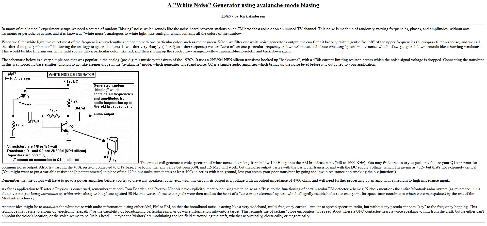
I filed the attached article image decades ago when (as a hobbyist) I was playing with zener generated white noise. Apologies if it's stuff you're already familiar with.