Hello, I am a 12th grade high school student working on a Sand Table, modeled after this project: https://www.instructables.com/Build-a-Mesmerizing-Sand-Table-a-DIY-Arduino-Maste/
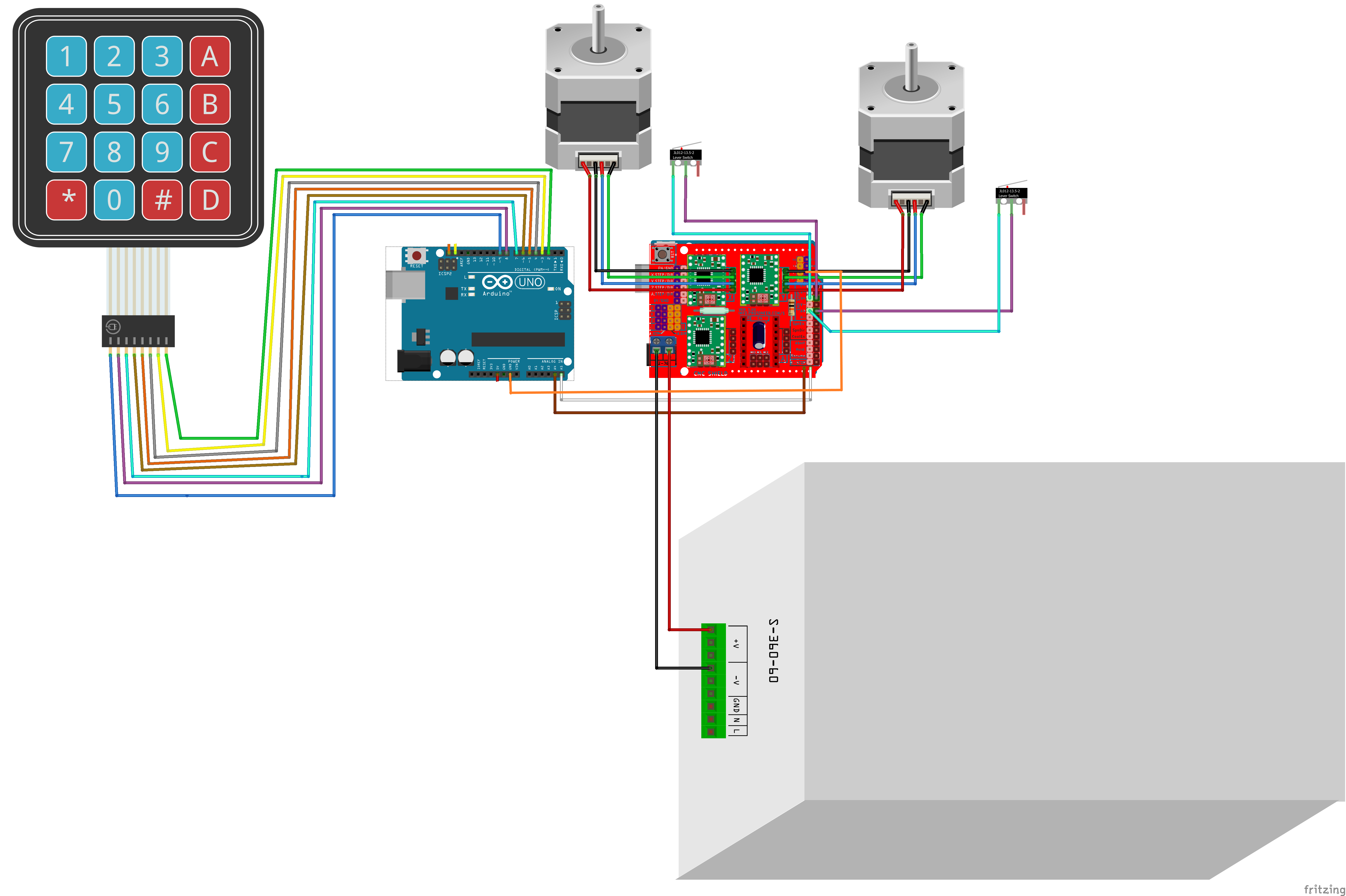
I am using an arduino uno with a keypad to communicate via I2C to an arduino uno and cnc shield, which controls the NEMA 17 stepper motors. I have attached an image, which is from this project: GitHub - maddaxlallatin/grizzlyGuide
The only difference between this wiring and mine is I have omitted the LCD screen and added a wire between the ground pins on the arduino and CNC Shield.

I have run into an issue with my stepper motors where they are turning in the wrong directions inconsistently. They were turning correctly at first, but then after I connected a wire between the two arduinos' GND pins, this issue has began. Even after removing the wire, it has persisted. On the serial monitor, I can see that it always runs the correct function, but it will frequently move in the wrong direction. I don't see a pattern in when/how the motors malfunction, so I am quite lost.
I am very new to this, so any help/suggestions are appreciated! Also, please let me know if I should provide more information about my project.
Here is the code for the keypad arduino:
#include <Wire.h>
#include <Keypad.h>

const byte numRows = 4;  // Number of rows on the keypad
const byte numCols = 4;  // Number of columns on the keypad

// Keymap for the 4x4 keypad layout
char keymap[numRows][numCols] = {
  {'1', '2', '3', 'A'},
  {'4', '5', '6', 'B'},
  {'7', '8', '9', 'C'},
  {'*', '0', '#', 'D'}
};

// Pin assignments for the keypad
byte rowPins[numRows] = {9, 8, 7, 6};  // Rows 0 to 3
byte colPins[numCols] = {5, 4, 3, 2};  // Columns 0 to 3

Keypad myKeypad = Keypad(makeKeymap(keymap), rowPins, colPins, numRows, numCols);

String input = "";  // Store input from the keypad

void setup() {
  Serial.begin(9600);  // For debugging
  Wire.begin();        // Initialize I2C as master
  pinMode(LED_BUILTIN, OUTPUT);
}

void loop() {
  char key = myKeypad.getKey();  // Get keypress from keypad

  if (key) {
    Serial.println(key);  // Print key to Serial Monitor for debugging
    digitalWrite(LED_BUILTIN, HIGH);
    delay(100);
    digitalWrite(LED_BUILTIN, LOW);
    if (key == '#') {
      // When "#" is pressed, send input to slave and reset input
      sendToSlave(input);
      input = "";  // Clear input after sending
    }
    else if (key == '*') {
      // When "*" is pressed, reset the input
      input = "";
    }
    else {
      input += key;  // Add key to input string
    }
  }
}

void sendToSlave(String data) {
  Wire.beginTransmission(9);  // Address of the slave (I2C address 9)
  Wire.write(data.c_str());   // Send the input string
  Wire.endTransmission();     // End transmission
}
And the motor control arduino:
#include <ezButton.h>
#include <Wire.h>
int num = 1;
int colour = 0;  //leds
int button = 0;
int delayMin = 1;
bool homing = false;
int change = 0;
int power = 1;
int pause = 0;
//int right=0;
//int arrayLength = 0;
//float slope = 0;
float m = 0;
float distance = 1;


int dx = 10; // for bounce
int dy = 5;


int width = 165;
int height = 190;
int buttonStateX = 1;
int buttonStateY = 1;
//x , y


//math diameter 15mm
// ONe rotation = 1600 pulses
//int incomingByte = 0;
// defines pins
#define stepPin 2  //x
#define dirPin 5   //x
#define enPin 8    //
#define stepPin2 3  //y
#define dirPin2 6   //y
#define green A0
#define blue A1
#define red A2
#define xSwitch 10
#define ySwitch 9
int speed = 800;
float rotations = 15;  //15mm per rotations = 1600 pulses
float x = 0;
float y = 0;
//int x1, y1, x2, y2 = 0;
int ranNum = 0;
//in mm
double turns = (distance / rotations) * 1600;


#define SLAVE_ADDRESS 9  // I2C address for this slave

void setup() {
  Serial.println("setup");
    Serial.begin(9600);
pinMode(LED_BUILTIN, OUTPUT);

  pinMode(green, OUTPUT);
  pinMode(red, OUTPUT);
  pinMode(blue, OUTPUT);
  // Sets the two pins as Outputs
  pinMode(stepPin, OUTPUT);
  pinMode(dirPin, OUTPUT);
  pinMode(stepPin2, OUTPUT);
  pinMode(dirPin2, OUTPUT);
  pinMode(enPin, OUTPUT);
  pinMode(ySwitch, INPUT_PULLUP);
  pinMode(xSwitch, INPUT_PULLUP);
  digitalWrite(enPin, LOW);


  digitalWrite(green, HIGH);
  digitalWrite(red, HIGH);
  digitalWrite(blue, HIGH);

  Wire.begin(SLAVE_ADDRESS);  // Initialize I2C as slave with address 9
  Wire.onReceive(receiveEvent);  // Register a function to handle received data

  Serial.println("finished setup");

  //home();
}

void receiveEvent(int bytesReceived) {
  String receivedData = "";  // Variable to store the received data

  while (Wire.available()) {
    char c = Wire.read();  // Read one byte from the I2C bus
    receivedData += c;     // Append the received character to the string
  }

  //Serial.print("Received: ");
  Serial.println(receivedData);
  digitalWrite(LED_BUILTIN, HIGH);
  delay(100);
  digitalWrite(LED_BUILTIN, LOW);
  delay(100000);
  interpretInput(receivedData); // Print the received data to the Serial Monitor
  //home();

}
void interpretInput(String input){

  if(input == "0"){
    down(5);
  }
  if(input == "5"){
    up(5);
  }
  if(input == "7"){
    left(5);
  }
  if(input == "9"){
    right(5);
  }

  if(input == "1"){
    up(1);
    delay(100000);
    down(1);
    delay(100000);
    left(1);
    delay(100000);
    right(1);
  }


  if(input == "4"){
    up(23);
  }
  if(input == "6"){
    left(20);
  }

}


void loop(){

}


/// Basic Functions
void stepperMotor(float distance) {
  turns = (distance / rotations) * 1600;
  for (int i = 0; i < turns; i++) {


    digitalWrite(stepPin, HIGH);
    digitalWrite(stepPin2, HIGH);
    delayMicroseconds(speed);
    digitalWrite(stepPin, LOW);
    digitalWrite(stepPin2, LOW);
    delayMicroseconds(speed);
    while (pause == 1) {
      //Serial.println("pause");
    };


    //if (power==1){return;}
  }
}


void right(float distance) {

  Serial.println("right");
  if (button > 0) { return; }
  digitalWrite(dirPin, HIGH);   // Enables the motor to move right
  digitalWrite(dirPin2, HIGH);  // Enables the motor to move right
  stepperMotor(distance);
  x = x + distance;
}


void up(float distance) {

  Serial.println("up");
  if (button > 0) { return; }
  digitalWrite(dirPin, HIGH);  // Enables the motor to move right
  digitalWrite(dirPin2, LOW);  // Enables the motor to move right/HIGH left/LOW
  stepperMotor(distance);
  y = y + distance;
}


void down(float distance) {

Serial.println("down");
  if (button > 0) { return; }
  digitalWrite(dirPin, LOW);    // Enables the motor to move right
  digitalWrite(dirPin2, HIGH);  // Enables the motor to move right/HIGH left/LOW
  stepperMotor(distance);
  y = y - distance;
}


void left(float distance) {

  Serial.println("left");
  if (button > 0) { return; }
  digitalWrite(dirPin, LOW);   //Changes the rotations direction left
  digitalWrite(dirPin2, LOW);  //Changes the rotations direction left
  stepperMotor(distance);
  x = x - distance;
}```