Interesting! So can you make the menu structure using this method to simulate those gifs? Obviously, we will change the existing text!
changing a character changes a character = making the >-symbol jump up and down
This jumping up / down will be initiated by keyboard-presses.
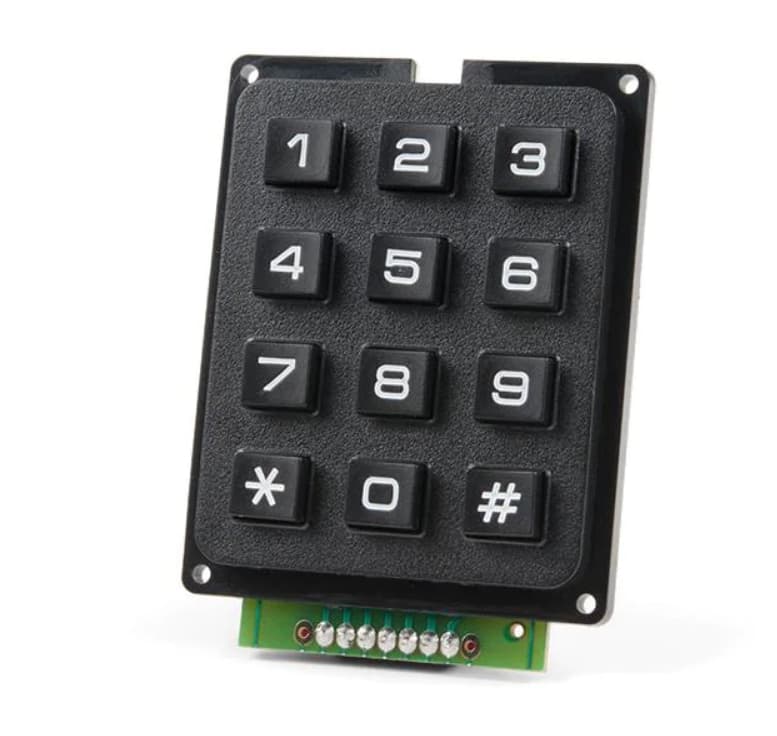
What is printed on the keys of your keyboard?
Can you post a picture of the keyboard?
So which keys to you want to use for
- arrow up/down
- enter / cancel
You pick, doesn't really matter haha. There will be one key for UP, one key for DOWN, one key for SELECT, and one key to return to the main menu
hm there are just the digits 0..9 # * not really symbolising the functions up/down select / return
Of course you could out a sticker on the keys
So let's say
star shall be return
double-cross shall be select
* return
# select
5 up
0 down
programming works this way:
wite a demo-code for one component
In this case the keyboard
take a keyboard-democode adapt it to print out the symbols of your keyboard
It is very likely that the internal wiring and how you connect the wires to IO-pins does not immidiately match the codes defintion.
there you will have to test and modify either the wiring or the code's definition which coordinate of line/columm is what character that shall be printed
So take the keyboard-example code and start testing
Keypad code:
#include <Keypad.h>

const byte ROWS = 4; //four rows
const byte COLS = 3; //three columns
char keys[ROWS][COLS] = {
  {'1','2','3'},
  {'4','5','6'},
  {'7','8','9'},
  {'#','0','*'}
};
byte rowPins[ROWS] = {5, 4, 3, 2}; //connect to the row pinouts of the keypad
byte colPins[COLS] = {8, 7, 6}; //connect to the column pinouts of the keypad

Keypad keypad = Keypad( makeKeymap(keys), rowPins, colPins, ROWS, COLS );

void setup(){
  Serial.begin(9600);
}

void loop(){
  char key = keypad.getKey();

}
this code needs a small modification for testing by printing to the serial monitor
make sure to adjust the baudrate of the serial monitor to 115200 baud
#include <Keypad.h>

const byte ROWS = 4; //four rows
const byte COLS = 3; //three columns
char keys[ROWS][COLS] = {
  {'1','2','3'},
  {'4','5','6'},
  {'7','8','9'},
  {'#','0','*'}
};
byte rowPins[ROWS] = {5, 4, 3, 2}; //connect to the row pinouts of the keypad
byte colPins[COLS] = {8, 7, 6}; //connect to the column pinouts of the keypad

Keypad keypad = Keypad( makeKeymap(keys), rowPins, colPins, ROWS, COLS );

void setup(){
  Serial.begin(115200); // make sure to adjust the serial monitor to 115200 baud
  Serial.println( F("Setup-Start") );
  Serial.println( F("press keys") );
}

void loop(){
  char key = keypad.getKey();

  if (key != NO_KEY) {
    Serial.println(key);
  }
}And this is a modified version of the Display democode that uses SafeStrings.
I have added a function
PrintTextToLCD(LineNr, Text)
which makes it more convenient to print to the display.
It does compile but the real test is with the real hardware
/****************************************************
       PINOUT: Arduino Uno -> Character OLED
****************************************************/
// The 8 bit data bus is connected to PORTD 0-7 of the Arduino Uno
// The 4 bit data bus is connected to PORTD 4-7 of the Arduino Uno

#define E_Pin 10
#define R_W   9
#define R_S   8

unsigned char InterfaceMode = 4; // 4 = 4-Bit parallel
// 8 = 8-Bit Parallel

#include <SafeString.h>

createSafeString(Line1_SS, 21); // reserve 20 bytes for the SafeString-variable
createSafeString(Line2_SS, 21); // reserve 20 bytes for the SafeString-variable
createSafeString(Line3_SS, 21); // reserve 20 bytes for the SafeString-variable
createSafeString(Line4_SS, 21); // reserve 20 bytes for the SafeString-variable


/****************************************************
                  Text Strings
****************************************************/

char const text4[] = ("   4-Bit Parallel   ");
char const text5[] = ("   8-Bit Parallel   ");

char const text6[] = ("ABCDEFGHIJKLMOPQRSTU");
char const text7[] = ("VWXYZabcdefghijklmno");
char const text8[] = ("pqrstuvwxyz123456789");
char const text9[] = (" <(' ')> || <(' ')> ");

/****************************************************
                Function Commands
****************************************************/

//-=-=-=-=-=-=-=-=-=-=-=-=-=-=-=-=-=-=-=-=-=-=-=-=-=
//  4-bit / 8-bit 6800 Parallel Interface
//-=-=-=-=-=-=-=-=-=-=-=-=-=-=-=-=-=-=-=-=-=-=-=-=-=

void latch() {                 // command to latch E
  digitalWrite(E_Pin, HIGH);
  delay(1);
  digitalWrite(E_Pin, LOW);
  delay(2);
}

void command(char i) {
  switch (InterfaceMode) {

    case 4: PORTD = i;
      digitalWrite(R_S, LOW);    // Command
      digitalWrite(R_W, LOW);    // Write
      latch();                   // Latch upper 4 bits
      i = i << 4;                // shift 4 bits
      PORTD = i;                 // Take lower 4 bits
      latch();                   // Latch lower 4 bits
      break;

    case 8: PORTD = i;
      digitalWrite(R_S, LOW);    // Data
      digitalWrite(R_W, LOW);    // Write
      latch();                   // Latch 8 bits
      break;
  }
}

void data(char i) {
  switch (InterfaceMode) {

    case 4: PORTD = i;
      digitalWrite(R_S, HIGH);              // Data
      digitalWrite(R_W, LOW);               // Write
      latch();                              // Latch upper 4 bits
      i = i << 4;                           // shift 4 bits
      PORTD = i;                            // Take lower 4 bits
      latch();                              // Latch lower 4 bits
      break;

    case 8: PORTD = i;
      digitalWrite(R_S, HIGH);              // Data
      digitalWrite(R_W, LOW);               // Write
      latch();                              // Latch 8 bits
      break;
  }
}

/****************************************************
                   Display Functions
****************************************************/

void clear_screen() {                   // clear display
  command(0x01);
}

void ret_home() {                       // Return to home position
  command(0x02);
}

void AssignTextTo_SS() {
  Line1_SS = "       Display      ";
  Line2_SS = "   International    ";
  Line3_SS = "   CHARACTER TEST   ";
  Line4_SS = "     Hello World    ";
}


void PrintTextToLCD(byte LineNr, SafeString& Text_SS) {

  switch (LineNr) { // set cursor to line

    case 1:
      ret_home();                 // First Line
      break; // immidiately jump down to END-OF-SWITCH

    case 2:
      command(0xc0);              // Second Line
      break; // immidiately jump down to END-OF-SWITCH

    case 3:
      command(0x94);              // Third Line
      break; // immidiately jump down to END-OF-SWITCH

    case 4:
      command(0xD4);              // Fourth Line
      break; // immidiately jump down to END-OF-SWITCH
  } // END-OF-SWITCH

  char Space = ' ';
  byte len = Text_SS.length();

  for ( int i = 0; i < len; i++) {
    data(Text_SS[i]);  // send characters to display
  }
  // clear until end of line with spaces
  for ( int i = len; i < 20; i++) {
    data(Space);          // clear with spaces until end of line
  }
}


void disp1() {                // DISPLAY TEXT
  clear_screen();
  PrintTextToLCD(1, Line1_SS);
  PrintTextToLCD(2, Line2_SS);
  PrintTextToLCD(3, Line3_SS);
  PrintTextToLCD(4, Line3_SS);
}


void disp2() {                // DISPLAY TEXT
  clear_screen();
  ret_home();                 // First Line
  for ( int i = 0; i < 20; i++) {
    data(text6[i]);
  }
  command(0xc0);              // Second Line
  for (int i = 0; i < 20; i++) {
    data(text7[i]);
  }
  command(0x94);              // Third Line
  for ( int i = 0; i < 20; i++) {
    data(text8[i]);
  }
  command(0xD4);              // Fourth Line
  for (int i = 0; i < 20; i++) {
    data(text9[i]);
  }
}

/****************************************************
               Initialization Routine
****************************************************/

void init1() {
  digitalWrite(E_Pin, LOW);
  delay(300);

  switch (InterfaceMode) {
    case 4: command(0x28);     //Enable 4-Bit Mode
      delay(5);
      break;
    case 8: command(0x38);     //Enable 8-Bit Mode
      delay(5);
      break;
  }
  command(0x08);             //Display OFF
  delay(2);
  command(0x01);             //Clear Display
  delay(2);
  command(0x06);             //Entry Mode set
  delay(2);
  command(0x02);             //Return Home
  delay(2);
  command(0x0C);             //Display ON
  delay(2);
}

/*****************************************************
            Setup Function, to run once
*****************************************************/

void setup() {
  AssignTextTo_SS();

  DDRD = 0xFF; // Enable pins on PORT D as outputs
  DDRB = 0xFF; // Enable pins on PORT B as outputs
  init1();
  delay(100);
}

/*****************************************************
            Loop Function, to run repeatedly
*****************************************************/

void loop() {
  disp1();
  delay(2500);
  disp2();
  delay(2500);
}Ok! Now for the menu structure when you can!
I could. I have quite a lot experience with programming in general but I haven't coded such a kind of menu for some years. This means I have to analyse it myself. How it works in detail.
I will do that but I will publish it only after you have made your "homework" of learning how coding if-conditions to print "up-key" "down-key" was pressed to the serial monitor is done.
Deal! My son loves this interactive learning haha! I'll see if his brother wants to join in on this too!
at my local time it is 1:30 pm. I will go to bed now.
I think you have some code to play with
Here is a more modified display-demo-code
This version uses more self-explaining names for functions and constants
Self-explainig names make commenting obsolete as the code is explaining itself.
This code compiles. But there is a chance that there is still a bug inside
This means you have to test it on the real hardware if it really works.
/****************************************************
       PINOUT: Arduino Uno -> Character OLED
****************************************************/
// The 8 bit data bus is connected to PORTD 0-7 of the Arduino Uno
// The 4 bit data bus is connected to PORTD 4-7 of the Arduino Uno

#define E_Pin 10
#define R_W   9
#define R_S   8

#define SecondLine 0xc0
#define ThirdLine  0x94
#define FourthLine 0xD4

unsigned char InterfaceMode = 4; // 4 = 4-Bit parallel
// 8 = 8-Bit Parallel

#include <SafeString.h>

createSafeString(Line1_SS, 21); // reserve 20 bytes for the SafeString-variable
createSafeString(Line2_SS, 21); // reserve 20 bytes for the SafeString-variable
createSafeString(Line3_SS, 21); // reserve 20 bytes for the SafeString-variable
createSafeString(Line4_SS, 21); // reserve 20 bytes for the SafeString-variable


/****************************************************
                  Text Strings
****************************************************/

char const text4[] = ("   4-Bit Parallel   ");
char const text5[] = ("   8-Bit Parallel   ");

char const text6[] = ("ABCDEFGHIJKLMOPQRSTU");
char const text7[] = ("VWXYZabcdefghijklmno");
char const text8[] = ("pqrstuvwxyz123456789");
char const text9[] = (" <(' ')> || <(' ')> ");

/****************************************************
                Function Commands
****************************************************/

//-=-=-=-=-=-=-=-=-=-=-=-=-=-=-=-=-=-=-=-=-=-=-=-=-=
//  4-bit / 8-bit 6800 Parallel Interface
//-=-=-=-=-=-=-=-=-=-=-=-=-=-=-=-=-=-=-=-=-=-=-=-=-=

void latch() {                 // command to latch E
  digitalWrite(E_Pin, HIGH);
  delay(1);
  digitalWrite(E_Pin, LOW);
  delay(2);
}

void command(char i) {
  switch (InterfaceMode) {

    case 4: PORTD = i;
      digitalWrite(R_S, LOW);    // Command
      digitalWrite(R_W, LOW);    // Write
      latch();                   // Latch upper 4 bits
      i = i << 4;                // shift 4 bits
      PORTD = i;                 // Take lower 4 bits
      latch();                   // Latch lower 4 bits
      break;

    case 8: PORTD = i;
      digitalWrite(R_S, LOW);    // Data
      digitalWrite(R_W, LOW);    // Write
      latch();                   // Latch 8 bits
      break;
  }
}

void SendCharToLCD(char i) {
  switch (InterfaceMode) {

    case 4: PORTD = i;
      digitalWrite(R_S, HIGH);              // Data
      digitalWrite(R_W, LOW);               // Write
      latch();                              // Latch upper 4 bits
      i = i << 4;                           // shift 4 bits
      PORTD = i;                            // Take lower 4 bits
      latch();                              // Latch lower 4 bits
      break;

    case 8: PORTD = i;
      digitalWrite(R_S, HIGH);              // Data
      digitalWrite(R_W, LOW);               // Write
      latch();                              // Latch 8 bits
      break;
  }
}

/****************************************************
                   Display Functions
****************************************************/

void clear_screen() {                   // clear display
  command(0x01);
}

void ret_home() {                       // Return to home position
  command(0x02);
}

void AssignTextTo_SS() {
  Line1_SS = "       Display      ";
  Line2_SS = "   International    ";
  Line3_SS = "   CHARACTER TEST   ";
  Line4_SS = "     Hello World    ";
}


void PrintTextToLCD(byte LineNr, SafeString& Text_SS) {

  switch (LineNr) { // set cursor to line

    case 1:
      ret_home();                 // First Line
      break; // immidiately jump down to END-OF-SWITCH

    case 2:
      command(SecondLine);
      break; // immidiately jump down to END-OF-SWITCH

    case 3:
      command(ThirdLine);
      break; // immidiately jump down to END-OF-SWITCH

    case 4:
      command(FourthLine);
      break; // immidiately jump down to END-OF-SWITCH
  } // END-OF-SWITCH

  char Space = ' ';
  byte len = Text_SS.length();

  for ( int i = 0; i < len; i++) {
    SendCharToLCD(Text_SS[i]);  // send characters to display
  }
  // clear until end of line with spaces
  for ( int i = len; i < 20; i++) {
    SendCharToLCD(Space);          // clear with spaces until end of line
  }
}


void disp1() {                // DISPLAY TEXT
  clear_screen();
  PrintTextToLCD(1, Line1_SS);
  PrintTextToLCD(2, Line2_SS);
  PrintTextToLCD(3, Line3_SS);
  PrintTextToLCD(4, Line3_SS);
}


void disp2() {                // DISPLAY TEXT
  clear_screen();
  ret_home();
  for ( int i = 0; i < 20; i++) {
    SendCharToLCD(text6[i]);
  }
  command(SecondLine);
  for (int i = 0; i < 20; i++) {
    SendCharToLCD(text7[i]);
  }
  command(ThirdLine);
  for ( int i = 0; i < 20; i++) {
    SendCharToLCD(text8[i]);
  }
  command(FourthLine);
  for (int i = 0; i < 20; i++) {
    SendCharToLCD(text9[i]);
  }
}

/****************************************************
               Initialization Routine
****************************************************/

void init1() {
  digitalWrite(E_Pin, LOW);
  delay(300);

  switch (InterfaceMode) {
    case 4: command(0x28);     //Enable 4-Bit Mode
      delay(5);
      break;
    case 8: command(0x38);     //Enable 8-Bit Mode
      delay(5);
      break;
  }
  command(0x08);             //Display OFF
  delay(2);
  command(0x01);             //Clear Display
  delay(2);
  command(0x06);             //Entry Mode set
  delay(2);
  command(0x02);             //Return Home
  delay(2);
  command(0x0C);             //Display ON
  delay(2);
}

/*****************************************************
            Setup Function, to run once
*****************************************************/

void setup() {
  AssignTextTo_SS();

  DDRD = 0xFF; // Enable pins on PORT D as outputs
  DDRB = 0xFF; // Enable pins on PORT B as outputs
  init1();
  delay(100);
}

/*****************************************************
            Loop Function, to run repeatedly
*****************************************************/

void loop() {
  disp1();
  delay(2500);
  disp2();
  delay(2500);
}
best regards Stefan
This should do:
#include <Keypad.h>

const byte ROWS = 4; //four rows
const byte COLS = 3; //three columns
char keys[ROWS][COLS] = {
  {'1','2','3'},
  {'4','5','6'},
  {'7','8','9'},
  {'#','0','*'}
};
byte rowPins[ROWS] = {5, 4, 3, 2}; //connect to the row pinouts of the keypad
byte colPins[COLS] = {8, 7, 6}; //connect to the column pinouts of the keypad

Keypad keypad = Keypad( makeKeymap(keys), rowPins, colPins, ROWS, COLS );

void setup(){
  Serial.begin(9600);
}

void loop(){
  char key = keypad.getKey();

  if (key == '5'){
    Serial.println("UP");
  }
  if (key == '0'){
    Serial.println("DOWN");
  }
  if (key == '#'){
    Serial.println("SELECT");
  }
  if (key == '*'){
    Serial.println("MAIN MENU");
  }
}
did you really try that? What was code / the precise pin mapping you tried?
Imho if you get the default LiquidCrystal working it makes your life far easier.
This is the code for the US2066
case 4: PORTD = i;
      digitalWrite(R_S, HIGH);              // Data
      digitalWrite(R_W, LOW);               // Write
      latch();                              // Latch upper 4 bits
      i = i << 4;                           // shift 4 bits
      PORTD = i;                            // Take lower 4 bits
      latch();                              // Latch lower 4 bits
      break;

    case 8: PORTD = i;
      digitalWrite(R_S, HIGH);              // Data
      digitalWrite(R_W, LOW);               // Write
      latch();                              // Latch 8 bits
      break;
  }
except for cursor-columm positioning the main thing is there
Is the standard LCD based on HD44870 doing the same thing?
two things that make me doubt:
waveshare wrote a library for the arduino Mega 2560 (uses 2560-specific ports)
I took a look into liquidcrystal.h/.cpp
cursor-positioning
HD44780
#define LCD_SETDDRAMADDR 0x80
void LiquidCrystal::setCursor(uint8_t col, uint8_t row)
 command(LCD_SETDDRAMADDR | (col + _row_offsets[row]));
US2066
#define SecondLine 0xc0
command(SecondLine);
//then start sending data
hopefully NOT! it will do it in "another" - yes "better" way -
for example the "liquid crystal" will not interfere with the lower 4 bits on port D - where we have on an UNO the serial pins, and LC will not disturb pin 2 and 3 which this code does as it writes the full 8 bits (even in 4 bit mode).
to me the control-commands seem to be very different
which would mean a lot of work to adapt it
0x80 + 0 + 0x40 is exactly the same what the example code (0xC0) does for the second row ... just saying.
You can either invest time to make the example code fit or get LiquidCrystal (or literally "any" other LCD lib) running which implements the official LCD API (known by most of the Arduino guys) and inherits from print.h. I think I don't have to explain to you what advantages this will bring for this and further projects.
I did not analyse the details of the offset-calculations. 0x40 in decimal is 64.
In the SU2066-code the rows start counting at 1
row 1: most upper (= first row) (in standard LCD row 0
row 1: one row below most upper (= second row) (in standard LCD row 1
etc.
does it still equal?
of course the fastest way to test is connecting the real US2066-driver LCD and flash a testcode
that uses the standard Liquidcrystal-library.
@ironmarvel : where did you get the code that makes an Arduino Uno work with the US2066-display?
The driver provided by the manufacturer newhaven makes use of Arduino Mega 2560-specific port-definitions.
best regards Stefan