I am looking into solutions to dim and switch on/off a LED strip based on an external trigger. I've looked into many commercially available solutions for this, however none really fit my needs. Having used Arduinos once before, I thought about building a custom circuit for this! Since I have very basic knowledge of circuit building and programming, I'm turning to you for help.
The LED strip I want to use is the ZM-4110-CW by JKL Components. It's a 12V DC white LED strip running with 75mA current that can be dimmed using pulse width modulation. It has its own internal current-limiting resistor. The external trigger I'm using can output voltages between 0- 4.096V with a maximum output current of 4mA. I'll be buying an Arduino Uno and a breadboard for this.
What I want to achieve is to have the LEDs switched off completely for a given time, then switched on at a specific light intensity, then switched off and so on. I would like the switching and dimming to be dictated by an external source giving 0 to 4.096 volts. Four or five different light intensities should be sufficient. I would like to run this without the board being connected to my computer.
It's a 12V DC white LED strip running with 75mA current
That seems a very low current. Are you sure that is not 75mA per LED?
It also seems odd that you need just a 5V PWM to drive this. That implies some electronics inside the strip. Can you post a link to this strip, use the chain link icon just right of the TV icon.
What about this sensor? I’d it a light sensor, if so which one are you looking to use, again a link please.
One problems with light sensors is that often the light from the LEDs affect this as well as he ambient light.
I'll be buying an Arduino Uno and a breadboard for this.
Didn't you come here for advice? Get a Nano or Pro Mini. Uno is not really breadboard compatible.
It also seems odd that you need just a 5V PWM to drive this.
Mike, the OP said pwm, didn't say 5V.
Sam, you will need a transistor to dim the 12V strip, I suspect. The model will be determined by the current, and I agree 75mA sounds low. Is it a series of modules in a string, and each module consumes 75mA? If so, how many modules?
I would like the switching and dimming to be dictated by an external source giving 0 to 4.096 volts
How will this external source dictate the timing and the intensity? Or will there be 2 or more for off time, on time and intensity?
The external source I'm using is controlled by a software (Anymaze to be exact). I've provided a link to their website so you can have a clearer idea of what this source is. Unfortunately, I have an older model that isn't on the website anymore. The software tracks rodents in a cage and can trigger different switches or analog outputs based on different parameters (time, position of animal, speed, and many others). My thought was to assign randomly a variable to each animal between lets say 1 and 4 and have them exposed to different light intensities based on the variable they were assigned (1 = low light, 2 = medium light, etc.). In the software, I can assign variables to analog outputs in volts, so if I could somehow dim the LEDs with this voltage it would be great.
My worries is that the Arduino Nano only goes up to 5V, would it be enough?
And when you post a link, please do not click the "Prevent this page from creating additional dialogs" checkbox; this is just a nuisance for people trying to follow the links.
OK, so it does require (only) 75 mA, and it operates at 12 V as each three LEDs are in series. It should indeed be nice and bright.
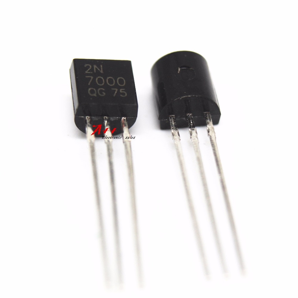
So you need a transistor to control it. Nowadays, a "transistor" generally implies that MOSFET would be the most appropriate choice. A 2N7000 should be inexpensive and should suit in this particular application as it is more-or-less a logic-level FET. For more current (it is cited as only a "Small Signal MOSFET"), there are better devices.
Aliexpress
You connect the source to your common ground between the Arduino and 12 V power supply, the gate to the Arduino output and the drain to the negative of the LED cluster, with the positive of the LED cluster to your 12 V. Add a 10k or 100k resistor between gate and source to keep the FET switched off while the Arduino is booting.
Ok, I'm starting to get a clearer idea of how this works. Basically the transistor just transposes the 5V PWM signal from the Arduino to the 12V supplied from the power. What would be the best option to provide power to the breadboard from a north american 120V AC wall socket?
Mike will tell you not to use a "solderless breadboard", I will tell you not to use "Vin" on the Nano. If you use a 12 V "wall wart" to power the LEDs, you want a switchmode "buck" converter module to derive the 5 V for the Nano. You could of course, use a second mains power supply such as a USB "phone charger".
Aliexpress