Library for ShiftBrite

blustang: Hey, that actually looks perfect. You probably will need only one, but it might not hurt to have two, especially if you plan to expand the system at some point.

Nachtwind: Each pixel has a PWM controller in it, data is pulled into one side and after 32 clocks, it comes out the other side. Each ShiftBrite is like a 32 bit shift register. You run the same six wires from one ShiftBrite to the next, each ShiftBrite adding 32 more bits to the register. If you had three ShiftBrites, you would be able to control all nine (3 red, 3 green, 3 blue) brightness individually by shifting out 96 bits with all the brightness data encoded into 10-bit words (plus two control bits per ShiftBrite). In order to change the brightness of one LED, you have to change the data for that LED, then refresh the whole array.

oh, i see.. thank you :0)
I was asking because i didnt see any controllers or anything in that project.

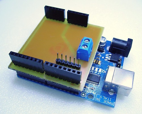
Yeah, I'm running it all off a Diecimila and a homemade shield. The power is injected with that blue terminal and the ShiftBrite cable plugs into the 6 pin header.

I think I smoked one of my shiftbrites by hooking up the supply voltage backwards. Polarized connectors don't help if you breadboard it incorrectly!

Don't suppose there's anything I can check before I salvage the LED is there?

Nope, the A6281 is very probably gone. Now, you COULD try replacing it...but that chip is really tiny. I hand soldered five of them and that was enough...but if you like a challenge it's a possibility.

Hi all here i have a chain of 8 SB and a arduino 10000 i'm using the chipey librart for SB but i have some concern about the SB.setPower function... how is it work? i have to call it once or i have to call 8 time for 8 SB? i try different solution and different value but noting notable happens.

Thanks

Quick question. I had all of this working pretty well, with only 1/2 of it done. Now that it is all done the chain does not seem to work. I can get the sample code at ShiftBrite RGB LED Module | macetech.com to work but as soon as i swap the leads around and upload the Knight Rider sketch nothing happens.

Any thoughts? Did i fry the board some how. I have a new Duemilanove board coming. which will be the board i mount in the control box under the hood. I guess i will try the new board when it gets here in a day or two.

here is a video of one scoop filled with light

Looks great...but what do you mean by "swap the leads around"? Oh...the labels in the earlier code may not be completely accurate...it might say "DI" next to the definition of "latchpin" etc. I was switching leads around too...let me go back in the thread, copy the code, and come back to edit this post....

#define clockpin 13 // CI
#define datapin 11 // DI
#define enablepin 10 // EI
#define latchpin 9 // LI

That's how it should actually be connected. I hope that was the problem. Don't forget ground...

Also, if you have any flickering problems with 32 LEDs, let me know. You could actually connect the controller to the middle of the chain and run both chains in parallel, that would just require me to delete some of the code. Let me know if you need any ideas for other changes to the code, too; maybe potentiometer control of speed, maybe a pushbutton to activate a few scans and then stop, etc. Or how about a startup pattern, all LEDs flickering together and slowly fading on, and then switching to the scan.

That was it. :slight_smile: She is working like a charm. I am going to work on getting the casing built the next few days so i can mount the leds inside and not worry about moving them around and possibly damaging the solder joints. Then i will start looking at the code :o and trying to understand how that works. :-?

I am not seeing any flicker at the moment, but i am running the chain with 2 of the power supply's got from you. One from each end. I am also waiting on the 2 converters i got off Ebay that i found earlier. i hope to get them in the next few days after that i will have to find a box to house the 2 Power supply's and the ardruino.

thanks

I found your newest youtube video and it looks great! You managed to solder those up pretty fast. I'm going to post some updated code that greatly improves the fadeout smoothness, right now I think you see the occasional stutter on the trailing end of the pattern.

I can explain the original code a little better, too. That "CenterWidth" number controls how wide the full-on region is. If you set that to the same width as one of your bars, then it would completely fill the bar before the trailing edge came into view. Alternately, setting it to 1 would just make a dot scanning back and forth with leading and trailing fades, more of a Cylon effect. Now, the edges are controlled with the KittLeadingEdge[] and KittTrailingEdge[] arrays. Each number corresponds to an LED of that particular brightness tacked onto the edge of the CenterWidth bar. You can actually add or remove numbers to get the effect you need, the code will automatically account for the changing array size. You could have a 10-led fading edge or even have a full bright dot and then a blank space.

The NewKittFill function pulls everything together. Here are the parameters:
NewKittFill(int dir, int FillSpeed, int FadeSteps, int red, int green, int blue)

dir: 0 for one direction, 1 or greater for reverse

FillSpeed: raw input to delay() function in the code, usable range seems to be 0 to 20 ms, it controls the time between each fade step

FadeSteps: the number of divisions between each LED position, as it shifts the pattern; it will mix the current and next LED colors according to the ratio of the virtual array position. usable range seems to be 1 (no fading) to 15, and it has a big effect on speed.

red, green, blue: 0 to 1023, brightness of each color in the full-on bar. the leading and trailing edges scale all the colors.

This is definitely still some rough code, probably could be optimized a lot.
I have got to say you are my new favorite person!!! :wink: I have been tweaking and testing for the past 2 hours and i still am trying to make my mind up. I had no idea the color and speed was going to be so simple. Even the Trailing and leading edges. BRILLIANT!!! Had the 2 edges 8 LEDs wide.

I LOVE THIS THING ;D

quick question, Would it hurt any thing if i was to mask the leds off and spray paint the PCB black? is there maybe a special paint. I am just trying to not have then stand out a lot while there off

Glad they're working so well for you...I believe if you masked the tops of the LEDs, a light coat ordinary acrylic spray paint (Krylon, etc) would not harm anything on the top of the PCB. You might want to mask the edge of the PCB on the first ShiftBrite so you can always tell where your connections are supposed to go.

This will make the bar look more like individual dots; normally a lot of light bounces to the sides and bottom and reflects off the PCB. If you wanted to enhance the spreading effect you could use white paint. I don't know if you plan to put a diffuser in front of the LEDs or not.

To help mix the colors and make the dots visible from all angles, you can find Glass Frosting Spray in a craft store. Spray this on after removing the mask from black paint. You might need a couple coats for the best diffusing. I have treated some ShiftBrites this way and it really helps make them a direct-view mixed color without reducing brightness.

I think i will try white paint. With way i am mounting the lights you wont see them head on and most of the light will be light that has bounced off of the hood scoop ducting and the to edge of the scoop. I had though about mounting them facing froward but i would reduce the Ram airs effectiveness and whats the point of having a hood scoop that does not work?

i will try the frosting spray i Had thought about sanding the inside edge of the tube but i was afraid to lose to much light. It does need to be defused if you start mixing colors. I have it set up right now to where it is the same color of the car 1023 blue and 350 green. and you can see the green and blue reflecting off of the walls in my office where when viewed for cretin angles the colors are not mixed

here is a cross section of the hoop to help you understand how i am mounting it. The orange doted line is the 1/4in thickness of the hood i plan to have the top of the tube level with the hood as it goes into the scoop. All the LEDs are still quit visible when standing in front of the car due to the fact that you look at a downward angle. Unless your 3ft tall you can see the LEDs no problem.

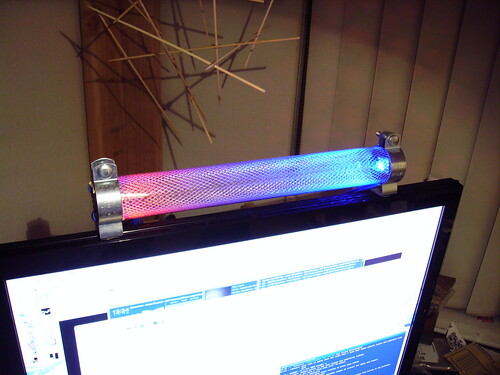
The diffusing should help spread more of the light toward the scoop entrance, though I am thinking at least 50% of the light will be heading back into the engine where no one will see it. I would consider tilting the bar towards the front a little bit, maybe 45 degrees or whatever fits with the room you have. Also, you can use fine steel screen as a nice reflector/diffuser. If you put some behind the LEDs, it might be a nice effect. This is a 12" tube of steel mesh with only two ShiftBrites in it:

I guess it would catch a lot of bugs though.

i would like to follow up my question

Hi all here i have a chain of 8 SB and a arduino 10000 i'm using the chipey librart for SB but i have some concern about the SB.setPower function... how is it work? i have to call it once or i have to call 8 time for 8 SB? i try different solution and different value but noting notable happens.

maybe reading better the old posts in this thread i suppose i have to call .setPower 8 time (suppose that .setPower strobe the latch pin)

Other issue now, i have some strange problem with my chain of 8 SB, i build a arduino sw that read data from serial at 57k when 24 bytes are present on buffer the sw star read 1 byte at time using the value in this way 1B=1R, 2B=1G, 3B=1B, 4B=2R, 5B=2G, 6B=2B and so on...
After loaded the data in meme i call 8 .setColor function from chipey but i have modified this moving away the lath pin controll, that now i call at the end of 8 setColor calls.

All work fine, i can from PC send data each 5-10ms for update the enterire chain.
But, this is the problem, some time a random LED in the chain and at random repetition time, flash in white... for a very little amounti of thime let say 10ms but i don't measure it than retur to color correctly...
what is strange is that this happens when i update the color pattern of my chain, infact if i not modify the color the issue don't exist at all, consider also in this case my PS sw is sending data each 10ms and the arduino sw receve and use it as usual the only difference is that the color request are always the same.
Any idea?
I guess something related to lachting the SB to earlyer or too late or for too long time.

Can you slow down the rate of commands to the chain and wait for the white LED to appear? Maybe have a button that sends one command each time you press it.

If the white LED appears and then disappears in place, and no other LEDs are affected, then there is a problem in the code. If the white LED appears and then slides along the chain and the LEDs after it also act strange, there may be a noise problem.

ok, i have slow down my refresh rate but the problem is still there. the flash involve only 1 led at time no propagation of strange colors over the chain.
i try also using your code KITT and the problem is present also in this case. Is difficult to view and high luminosity level i modified your sequence putting this in the void loop

NewKittFill(0, 60, 7, 90, 0, 0);
delay(200);
NewKittFill(1, 40, 7, 90, 0, 0);
delay(200);

here running with this parameter the problem apper 1-2 times on 10 complete fade, seem to be more frequent with speed set to 40 and when the chain is fading out.
Here i have a chain of 8 SB so i modified also the definition of KITT in this way

#define NumLEDs 4
#define CenterWidth 2

Hello, Things are coming along great. Work has been a little busy so i have not had a lot of time to work on this but i am getting back to it.

I was wondering on the minimum wire gauge. I am making 2 bars of 22 LED each and i need to connect them in the center. Using 2-3in pieces of wire with connectors so i can disconnect them for mounting. I am planing on soldering the wire direct to the board and going out the side of the housing to the connectors, one male one female.

Also along the same lines of the wire size. I have been thinking i would mount the control box right to the under side of the hood this would be a shot run of wire 1ft max. This way all i need to do is run the power and ground up from the engine compartment and up the under side of the hood. Now if i wanted to mount the box on the fender of the car what size wire would i need to run from the control box to the LED's the length of these wires would be 4-5ft. could i get away with 26-28 gauge maybe smaller. Cat5 cable maybe?

thanks

I would recommend shielded wire if you plan to run the control cable that far, especially through an engine compartment. The ShiftBrite control signals are only TTL and noise in the control lines will definitely affect them. I'd try to put the Arduino as close to the chain as possible, depending on how much room you have under the hood.

Probably best to stick with 24 or 22 gauge or better for the power connections....