I was looking at some 5ma fuses over at digikey and they all run $11 or more per piece! Are there any cheaper options? It doesn't necessarily have to be a fuse.. I just need a way to prevent the current from spiking up over 5mA (3mA would be even better).
I'm using a LM334 current source to deliver 1-2mA. If for some reason it starts to deliver more than 3-4mA, it would be dangerous (for my application).
Fuses will NEVER prevent current from spiking. Usually they are way slower than any electronic circuit they are designed to protect. If you need to be absolutely sure that you current is limited fuses are the wrong approach.
Current is not forced into a system - it is DEMANDED by whatever is connected to the power supply. If you feel that you might get "spikes" then you need to look at what is causing these within your demand circuit and cure the problem there.
Perhaps if you provided more information on your application we may be able to provide constructive suggestion.
Your best bet would to sense tne current and shut it down if you like a mosfet powering it all, definetly faster than a fuse
you could probably make a separate circuit with a sort of current sense shunt, comparator and one shot 555 timer to drive a master mosfet off, and then just. Reset the 555 and continue
r34p3rex:
I was looking at some 5ma fuses over at digikey and they all run $11 or more per piece! Are there any cheaper options? It doesn't necessarily have to be a fuse.. I just need a way to prevent the current from spiking up over 5mA (3mA would be even better).
I'm using a LM334 current source to deliver 1-2mA. If for some reason it starts to deliver more than 3-4mA, it would be dangerous (for my application).
For current limiting, a PTC resettable fuse is quite convenient. However, they sill still take a second or so to trip (more, depending on brand/model and amount of overcurrent.)
However, as someone else has said -- what would draw the additional current? Do you expect to suddenly have a short circuit somewhere? Can you design that current draw out?
Grumpy_Mike:
Yes but you can't get any that trip anywhere close to 5mA. The smallest I have seen is 300mA.
FWIW, you can go lower than that. For example, Digikey carries some SMD polyfuses with a hold current of 50mA and a trip current of 150mA. See here.
That said, I try (and the emphasis is on try, as I can't hold a candle to the likes of Grumpy_Mike) to design my circuits so that the usual parade of spikes, transients, etc. will not do anything harmful and that components will survive a 'trip' condition long enough for the fuse to actually do some good. Whether or not to use a PTC vs. a traditional fuse and under what circumstances is also a topic that may or may not require several pints of beer to resolve.
As for inexpensive low-amp fuses, I have had good luck in the past securing 10mA fuses from Allied Electronics, IIRC and other surplus dealers. They tend to be small round cylinders with matching plugs for the PCB. Might be worth a look.
For current limiting, a PTC resettable fuse is quite convenient.
Yes but you can't get any that trip anywhere close to 5mA. The smallest I have seen is 300mA.
The lowest available Ihold on DigiKey is 6mA, and Itrip is 14mA.
Note that they have significant resistance of their own for those values.
Here is a through hole part that's close (but more expensive, at 3-6 dollars) and rated 1000 Volts:
The lowest available Ihold on DigiKey is 6mA, and Itrip is 14mA.
I think you are miss reading the data sheet on that one.
For a current of 14mA it will take in excess of 200 seconds to blow, in fact the graph on page 5 of the data sheet showing switching time against current hardly shows the time at such low a current. To get a switching time of one second the current needs to be in excess of 1 Amp.
These devices are designed to be used in mains applications where the voltage is very much higher than the OP is talking about. To protect a device against an over current of 14mA it is totally useless. They are meant to do things like prevent fires when components fail or partially fail in a power supply.
A poly fuse is not going to protect anything from excess current if the device will be killed with excess current by any other mechanism than over heating.
Any fuse works by the action of generating heat in the component and using that heat to affect the physical proprieties of the component that in some way will restrict the current. With a wire fuse the heat melts the wire and then gravity pulls the molten wire apart. With a poly fuse it is the resistance of the material that gets changed with the heat.
A poly fuse is only good for a certain number of blows and the characteristics of them changes with each blow. The data sheet on the device you linked only guarantees to keep the characteristics within 25% for 100 tripping of the fuse.
The lowest available Ihold on DigiKey is 6mA, and Itrip is 14mA.
For a current of 14mA it will take in excess of 200 seconds to blow, in fact the graph on page 5 of the data sheet showing switching time against current hardly shows the time at such low a current. To get a switching time of one second the current needs to be in excess of 1 Amp.
I went by the parametric search feature. I also said that they'll typically take longer than you want to actually blow.
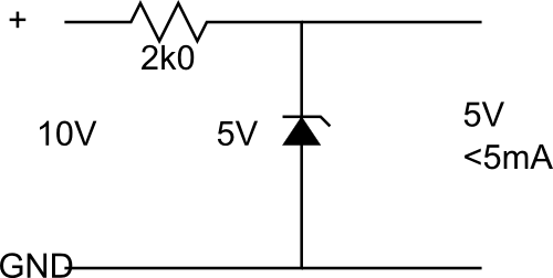
Perhaps the easier way of limiting current is to simply make it impossible to draw too much. If you need 5V at 2.5 mA, but you can accept up to 5 mA, simply design a power supply with those characteristics. For example, a 10 V power supply with a 2 kOhm resistor will generate no more than 5 mA of current. Put that across a 5 V Zener diode, and you know that the output will never be more than 5V (at the cost of some idle power consumption.)
And that folks is what one calls a "zener barrier". Slightly more simple than those used to provide "intrinsic safe circuits" which limit both current and voltage into areas of explosive atmospheres. The simpler commercial ones generally use two resistors, two zeners and a fuse.
Yes but that only limits the current to a zero impedance load. The problem is that it will also starve current from a real load.
Most of this depends on the actual load and the 'spiky' nature of current pulses that the OP was concerned with.
As the OP seems to have gone away or chooses not to reveal the nature of the load all we can do is offer incomplete solutions.
Hello all. I don't mean to hijack the OP's thread but I find myself with the same question regarding 5ma fuses. In my case -and I'm guessing in his too- it's for a tDCS device. If you look up 'GoFlow' you'll see they are trying to develop a DIY tDCS kit. It, they and the approach in general have gotten a lot of attention in the past few months and they've just made their schematic available. Naturally you will have some people who don't know much or anything about electronics now taking a keen interest. Myself included.
In broadest terms, in tDCS a positive electric field is shown to increase cortical excitability while a negative field can reduce it. Much like imposing an uphill or downhill gradient. This has been shown to have a number of persistent benefits with an astonishing lack of side effects in the literature. So far at least. I've waited half a decade before chancing it myself.
While I presently make do with a 9v cell and a 4.7k resistor, variations in skin conductance must certainly limit it's effectiveness. IIRC anything below about 45 micro-amps/cm2 at the electrode just makes a tingle. Luckily nothing less than a hundred times as much has caused injury in lab animals so a 5 or even 10ma fuse (dependent on electrode area) that takes a few moments to work shouldn't be a problem. Professional units can output up to 10ma anyway and therefore this value is probably quite conservative. Probably.
Incidentally, it occurs to me I assumed the 4.7k resistor would run to infinite resistance if it fails. I did verify it before soldering and do periodically check it but it would be nice to know if I'm right on that. (!)
Designing medical devices is a very different field from hobby electronics. If that's what you're doing, worrying about a resistor failing short (instead of failing open) is something you have to do, but it's not the only thing. Personally, I wouldn't trust a DIY medical device for much of anything. If it's actually safe and effective, it will show up at a cheap price at my local Rite-Aid soon enough. If it doesn't, then perhaps that safety/effectiveness is not at the point where someone would risk a business on it, and if that's the case, I certainly wouldn't risk my personal safety on it.
Incidentally, it occurs to me I assumed the 4.7k resistor would run to infinite resistance if it fails. I did verify it before soldering and do periodically check it but it would be nice to know if I'm right on that. (!)
No a resistor can fail short as well as failing open.
This tDCS is for real. It's not going to cure AIDS or fill potholes but results have been reproduced. Right now the field is wide open -and all over the place. The (business) students at GoFlow are not be best example of the approach but are an indication of how much interest is out there. As I understand it, they started out as/still are a student project. Again, a project of a group of business students. "Snake oil" seems entirely fair.
I really only mentioned them in particular since they've made the news a lot lately and had just released a full schematic. I was double checking their notations and looking for part sources when Google turned up this thread. (I don't know much but their 'schematic' in the Make post about them was pretty stupid.)
The point is that any voltage sent into the head via contact pads is mainly going to get a current go through the skin from one contact to another. The brain is encased in a skull, which is made of bone which is not a very good conductor. So there is little chance of passing any current actually through the brain with this method.
I hear You guys. Believe me I watched progress for years before putting my noggin on the block. The highest current anyone has studied seems to be 2ma. The skull does indeed block most of the current but that tiny remainder is what does he job. Some electrode 'montages' put the contalatteral reference electrode off the skull entirely, on the arm or shoulder for instance. Their was concern this may run potentially deadly currents through the brain stem though subsequent research has shown otherwise.
I knew 7ma could stop a heart going into this, I never entertained the slightest thought of placing electrodes acros my heart...and as I said I let a number of studies pile up for years before believing it can be done on the head safely. This new info about what I thought was a safe assumption does put some runs in my safety net.
I suppose a pair of resisitors in parrellel would be best/simplest for a newb like me though clearly not ideal? It does seem odd that the safe tolerences are that wide considering what's being worked on.... I'll just have to keep checking resistance before each use until I can handle the real fixes. Fact is I probably would regardless. Funny. How many of us do a 'preflight' on our cars before every drive?