Why connect a solar panel to an analogue pin.
Just connect solar (+) through a 10k resistor (for some pin safety) to a digital pin.
No internal pull up/down needed either. A solar panel turns into a load when it gets dark.
Leo..
1 Like
Hi,
All of the pins on my IC are used i just have this adc pin left for solar usage.
I tried the idea of connected solar through 10k to digital pin, the issue here is the resistor eats up the current and it would result into slow charging, that is my main issue
I will send you my main code.
float voltage;
#ifndef cbi
#define cbi(sfr, bit) (_SFR_BYTE(sfr) &= ~_BV(bit))
#endif
#ifndef sbi
#define sbi(sfr, bit) (_SFR_BYTE(sfr) |= _BV(bit))
#endif

void setup(){
clockdiv();
setup_watchdog(7);
}

void loop(){
wdt_reset();

solar_detects();
  if(voltage<=1)   //if not LOW means daytime
  {
    wdt_reset();
    //analogWrite (solarPin, HIGH);
    digitalWrite(led,LOW);
    radio.stopListening();
    radio.powerDown();
    selfBlink=false;
    sync=false;
    Stop=true;

  //  sleep_sys();
    //delay(2000/16);
  }
    //if ((voltage>=2) && (Stop==true))
// if LOW means nighttime

  else
  {
    // f_wdt=0;
   // analogWrite (solarPin,LOW);
    Stop=false;

    radio.powerUp();
    radio.startListening();
   }


void solar_detect(){
ADCSRA|=(1<<ADEN);
   sensorValue = analogRead(solarPin); // Solar Panel Positive PIN connect to A0
   voltage = sensorValue * (3 / 1023.0);
}

void clockDiv() //since we r using external 16Mhz clock, the clocking speed will be extremely high, in order to reduce it we must divide clock.
{
    cli();
    CLKPR  = 0x80;               //0x7f gives high freq than 0x8, 0x00 gives lowest freq
    CLKPR  = 0b00000011;         // clockDiv must not be used if NRF24lo1 auto-reset system is there. //0011(CLKPSO) 8MHZ, 0100(CLKPSO)16MHZ
    ADCSRA = 0;
   PRR |= (1<<PRADC);
    sei();


}


}
I have used 8MHZ external clock and have divided it internally into to reduce power consumption.
Now i need to turn ON (ADSCRA) register only for reading analog and off in the rest of the code. How do i do that.
EDIT: I have resolved the battery issue now it is working perfectly with external battery also but the adscra register problem is still there, the program is not working as intended.
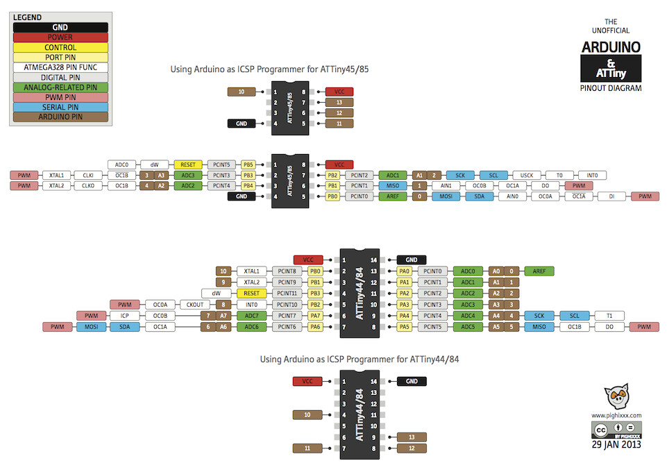
Yes, i removed serial command and changed solarpin to physical pin 10 of attiny and led to physical pin 6 of attiny
No, it is running at 8mhz with divided clock to reduce power consumption. The battery voltage is ok for it.
i resolved the battery issue now i have adcsra register problem.
That makes no sense.
You're not charging the battery through the analogue pin, or are you.
The solar panel should connect to a charging circuit, to safely charge the battery.
The solar panel could also connect through a resistor or voltage divider to an analogue pin, to detect day/night.
Please provide a full circuit diagram.
Leo..
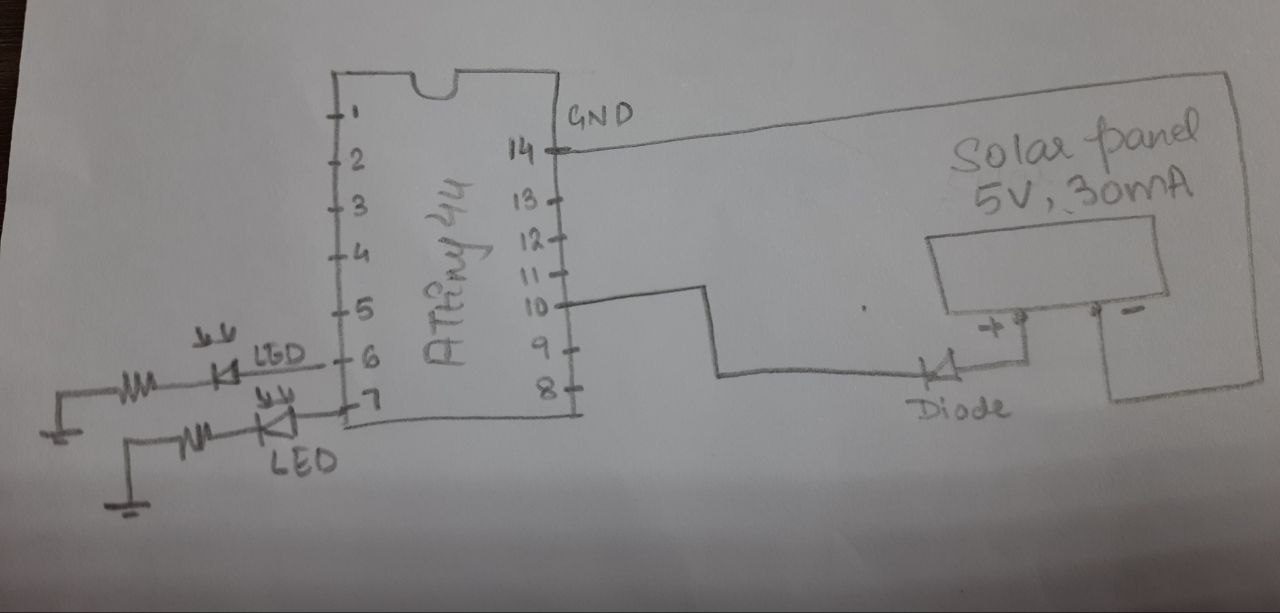
Now, the positive side of solar is going directly to IC physical pin 10 whereas, the negative goes to ground.
In order to avoid any reverse current i have connected one diode at positive side of solar panel. It is a very simple prototype. Handling the battery voltage code is already there.
Your basic circuit shows no solar backflow protection diode and no connection to the battery.
So the battery must get it's charge through the pin protection diodes of the Atmega chip.
This is BAD.
Day/night detection should be on the panel side of the backflow diode, while the battery and charging circuit should be on the other side of that diode.
How do you control battery charging. You can't just connect a 4volt panel to a LiPo battery.
Leo..

Hi, @anon45846334
Can you please draw a readable and accurate schematic with ALL your components.
Use proper pinout names and layout.
Thanks.. Tom... ![]()
![]()
![]()
![]()
PS. if your CAD package does not have your component, then please hand draw your circuit for clarity.
i will also share my recent code.
int solar = 3;
int yLed = 7;
int wLed = 6;
unsigned long sensorValue =0;

void setup(){
//clockDiv();
pinMode (solar, INPUT);
pinMode (yLed, OUTPUT);
pinMode (wLed, OUTPUT);

}

void loop(){
  sensorValue = analogRead(solar);
float voltage = sensorValue * (3 / 1023.0);

if ( voltage>=2.5){ //day
digitalWrite (yLed, HIGH);
digitalWrite (wLed, LOW);
}
if (voltage <=1){ //night
  digitalWrite (yLed, LOW);
  digitalWrite (wLed, HIGH);
}


}
EDIT:
i forgot to connect vcc and gnd to main battery in the drawing.
Hi, @anon45846334
Where on your schematic are the other pins used and what are they connected to?
Tom... ![]()
![]()
![]()
![]()
I see no connections to pins 1-5 8,9,11,12,13
I see no connection to Vcc pin 1
I see no battery
to charge the battery there will need to be a connection
capable of passing charging current
between solar panel ground and battery -ve ... and ..
between solar panel + and battery +
with some electronics that manages the battrey charging current
I think even explaining this project is beyond your current level of ability.
Oh you need to see the entire schematic, i thought it was just solar connected you wanted to

My issue is not here the circuit is working perfectly, the problem is with solar .
Now the code is working fine in low power mode but it is not waking up
#include<avr/wdt.h>
#include <avr/io.h>
#include <util/delay.h>
#include <avr/sleep.h>

#ifndef cbi
#define cbi(sfr, bit) (_SFR_BYTE(sfr) &= ~_BV(bit))
#endif
#ifndef sbi
#define sbi(sfr, bit) (_SFR_BYTE(sfr) |= _BV(bit))
#endif


volatile boolean f_wdt = 1;
int solar = 3;
int yLed = 7;
int wLed = 6;
unsigned long sensorValue =0;
float V;


void setup(){
clockDiv();
pinMode (solar, INPUT);
pinMode (yLed, OUTPUT);
pinMode (wLed, OUTPUT);
 setup_watchdog(7);

}

void loop(){
    wdt_reset();


//if (ADCSRA=1) {
sensorValue = analogRead(solar);
V = sensorValue * (3 / 1023.0);
//}


if (V>=2.5){ //day 2.5
//
 digitalWrite (yLed, LOW);
 digitalWrite (wLed, LOW);
 sleep_sys();
 //f_wdt=0;
}
if ((f_wdt==1)&& (V<=1)){ //night
f_wdt=0;

digitalWrite (yLed, HIGH);
digitalWrite (wLed, HIGH);
}


}


 void clockDiv() //since we r using external 16Mhz clock, the clocking speed will be extremely high, in order to reduce it we must divide clock.
{
    cli();
    CLKPR  = 0x80;               //0x7f gives high freq than 0x8, 0x00 gives lowest freq
    CLKPR  = 0b00000011;         // clockDiv must not be used if NRF24lo1 auto-reset system is there. //0011(CLKPSO) 8MHZ, 0100(CLKPSO)16MHZ
   // ADCSRA = 0;
   //PRR |= (1<<PRADC);
    sei();


}


void sleep_sys() {

cbi(ADCSRA,ADEN);

  set_sleep_mode(SLEEP_MODE_PWR_DOWN);
  //PRR |= (1<<PRADC);
   ACSR |= _BV(ACD); // Disable analog comparator
  ADCSRA &= ~_BV(ADEN); // Ensure ADC is indeed disabled
  PRR |= _BV(PRTIM0) | _BV(PRTIM1) | _BV(PRUSI) | _BV(PRADC);
  //ADCSRA=0;
  sleep_enable();

  sleep_mode();

  sleep_disable();
  //PRR |= (1<<PRADC);
  sbi(ADCSRA,ADEN);

}


void setup_watchdog(int ii) {

  byte bb;
  int ww;
  if (ii > 9 ) ii=9;
  bb=ii & 7;
  if (ii > 7) bb|= (1<<5);
  bb|= (1<<WDCE);
  ww=bb;

  MCUSR &= ~(1<<WDRF);
  // start timed sequence
  WDTCSR |= (1<<WDCE) | (1<<WDE);
  // set new watchdog timeout value
  WDTCSR = bb;
  WDTCSR |= _BV(WDIE);
}


ISR(WDT_vect) {
  f_wdt=1;

}
This just works once then an external reset is required
Where did you get these values? Take your panel and meter outside in full sun and measure real values.
With nothing connected to the panel output but the voltmeter, what's the voltage?
With nothing connected to to the panel output but your ampmeter, what's the current?
When measuring the voltage the output current will be 0A.
When measuring the current the output voltage will be 0V. You should get a voltage drop across the diode. Short the panel output and measure the voltage across the diode.
Let's assume you measured 40mA and the diode voltage is 0.8V. One would think if you place a 45 ohm resistor across the panel output you would measure 1.0V across the resistor but it doesn't work that way with a solar panel. It's neither a stiff current nor stiff voltage. You will measure >1V.
You will need to place a small value resistor across the panel output. Start with 45 -50 ohms. measure the full sun voltage. Move your hand over the panel to create a shadow. Play around with the resistor value until you get something you can work with. My guess is somewhere around 30 ohms will work.
You basically want to put the panel to where it would be charging a depleted battery
Edit: Never mind. I now understand you are trying to detect sunlight and charge a battery with the same panel. Not sure why an LDR isn't in order. You could measure the panel output current and trigger on that. Or use a 10k LDR , 50k resistor and use the 1.1V internal reference.
Hi, appreciate your long reply.
is it possible for you to write to small code to measure the panel output current and trigger on that.
I am already working on it. see
int solar =A0;
int readVal;
float voltage=0;
int delayTime = 500;
int led =8;


void setup() {
  // put your setup code here, to run once:
pinMode (solar, INPUT);
pinMode (led, OUTPUT);

Serial.begin(9600);
}

void loop() {
  // put your main code here, to run repeatedly:
readVal = analogRead (solar);
voltage = (4./1023.)*readVal;
Serial.println(voltage);
delay (delayTime);
if(voltage>=4.5){
  digitalWrite (led, HIGH);
}
else{
  digitalWrite (led,LOW);
}
}
This a very basic code that i just wrote, it worked fine with constant 5v from arduino, but the moment i use battery it has issues.
i know that it is because of the voltage difference n therefore, i am looking for something through which i can read battery voltage. something like:
(Battery voltage/1023) * readValue;
You would need a current sensor.
Read my edit above. I just changed it to include using the internal voltage ref with an LDR and a high value resistor. Why are you avoiding an LDR?
Because during the daytime, the battery must charge, that is the main reason behind using solar panel.
You are using a 1S LiPo and are having issues because the Vbatt readings of the LiPo are not up to snuff, correct?
Where does P1 connect to? Just Vbatt?
A 1S1P LiPo is not going to work very well. Expecting stable V readings from this project with the posted schematic from post#38 is not going to work out well for you. If the Vbatt to the MCU was regulated with a 3V3 LDO then yes, I can see it working.
Plus it's wild to think that I want to run my project on batteries but I want to drive LED's brightly and I want my project to run for 6 months!
If you want to detect daylight use a LDR or a photodiode.
Where is the charge controller? Please post the entire schematic. Using a solar charge controller, either PWM or MPPT, will allow the OP to do the thing.
So let me guess the solar cells output during the day is to go directly to the LiPo's?
1 Like