Hello everybody!
I'm here for the first time, and some questions may sound dumb, I'm sorry for that.
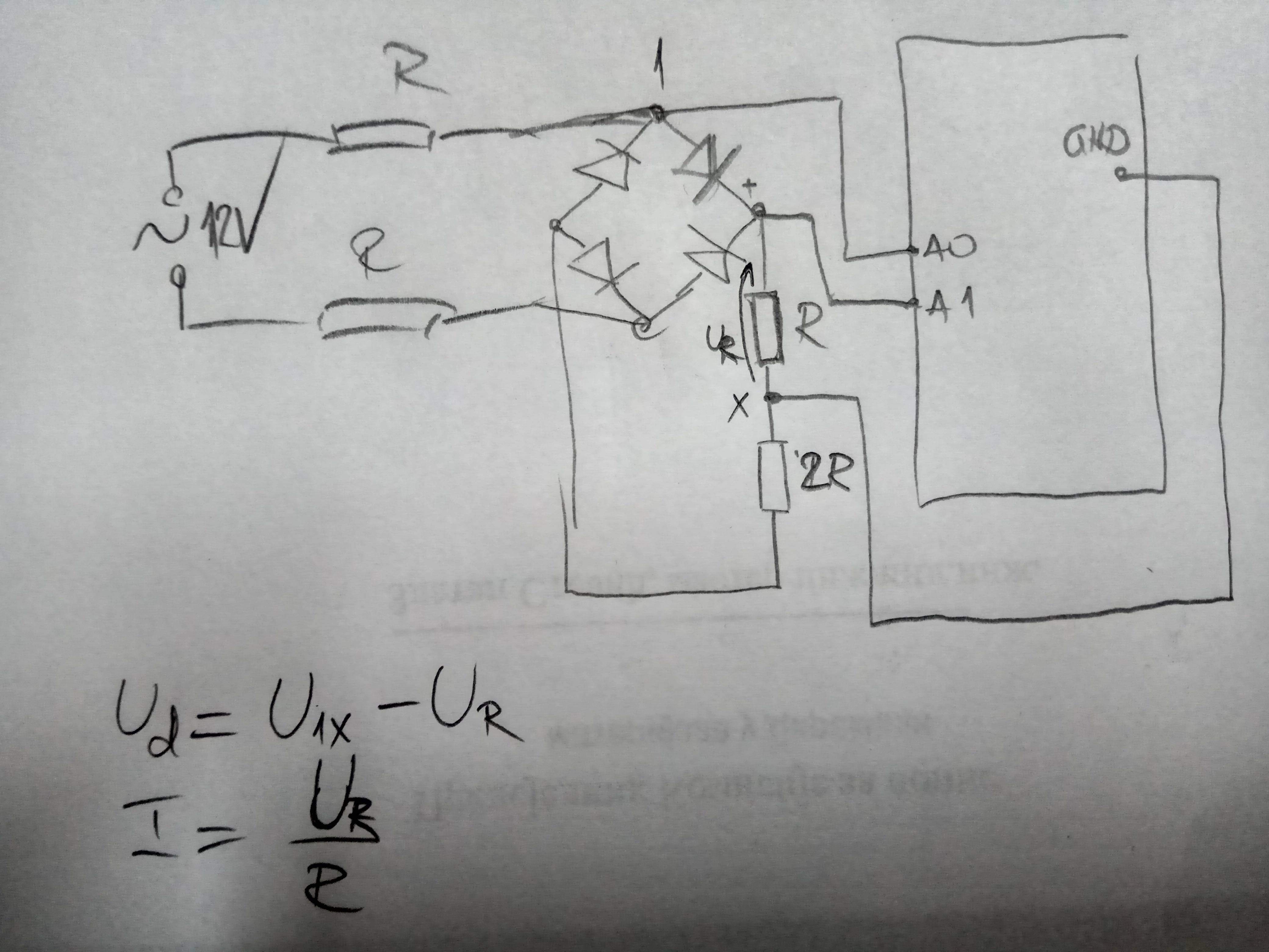
I would like to use arduino to get the wave form of the diode bridge voltage, and later to analyse it for harmonics etc.
I have 230/12V transformer, the rectifier, and then the voltage divider. On one of the resistances of the voltage divider should have peak value of the voltage of about 4V. May I connect one side of that resistance on A0 and the other on the GND?
Similarly in another project, I would like to get U/I characteristic of the diode, by changing current with a pot, and measuring the current (actually voltage on the proper resistance) and the voltage on the diode. Is it advisable to connect one side of the diode to A0 and the other on GND, and again one side of the resistance to A1 and the other to GND?
The configuration on the schematic is good. (But note that unloaded transformer may have considerably higher voltage than nominal.)
Draw a schematic for the diode measuring circuit. I think it cannot be really made as described.
I know I can get more than 13,5V if transformer is unloaded, thank you.
Are you aware that even supposing the output of the transformer is 1VAC as measured at the terminals then the peak will be 1.414 times* as much, so almost 17V, less whatever the diodes drop?
*Square root of 2.
PerryBebbington:
Are you aware that even supposing the output of the transformer is 1VAC as measured at the terminals then the peak will be 1.414 times* as much, so almost 17V, less whatever the diodes drop?
*Square root of 2.
Yes, of course, I know that. Peak values of input signals should be less then 5V, not mean or rms, thank you
Step down your signal to max 1.1V and use the internal ADC reference, for more stable output (that way you're not affected by fluctuations in the 5V supply).
I assume you know that rectification generates harmonics? And the voltage-drop across the diodes too? (Only a pure sine wave has no harmonics.)
If you want to measure the harmonics of the original sine wave you can use a bias circuit (2 equal-value resistors and a capacitor) to bias the input at 2.5V, then another series resistor to make another "AC" voltage divider to bring the peak-to-voltage down to 5V or less. (Then you can subtract-out the bias in software or if you're using FFT it will "fall into" the 0Hz bin where you can ignore it.)
You should be able to measure the strong harmonics resulting from rectification but I doubt you'll be able to measure any harmonics on the actual power line using the Arduino. ...That's just my gut-feeling.
May I connect one side of that resistance on A0 and the other on the GND?
The Arduino always measures relative to it's ground. And, as you know it can be damaged by negative voltages or voltages greater than +5V, again relative to it's ground.
The Arduino ground doesn't have to be connected to earth ground. For example, a battery-powered multimeter just has positive and negative (or a "common") connection. There is no actual "ground", although there is an internal ground/common which may be connected to the negative/common terminal. AC-powered multimeters have an isolated power supply.
You do have to "be careful" if you're using the Arduino's USB connection because it has a connection to external-ground and possibly to earth-ground. (If a multimeter has a USB port, it's optically isolated.)
The schematic from post #2 won't work. Arduino's GND is at 2/3 of the bridge output. Assuming 18 V peak voltage and no diode forward drop (there is minimal load after all) pin A0 will "see" voltages from -12 to 6 V and A1 from 0 to 6V. Either is not safe.
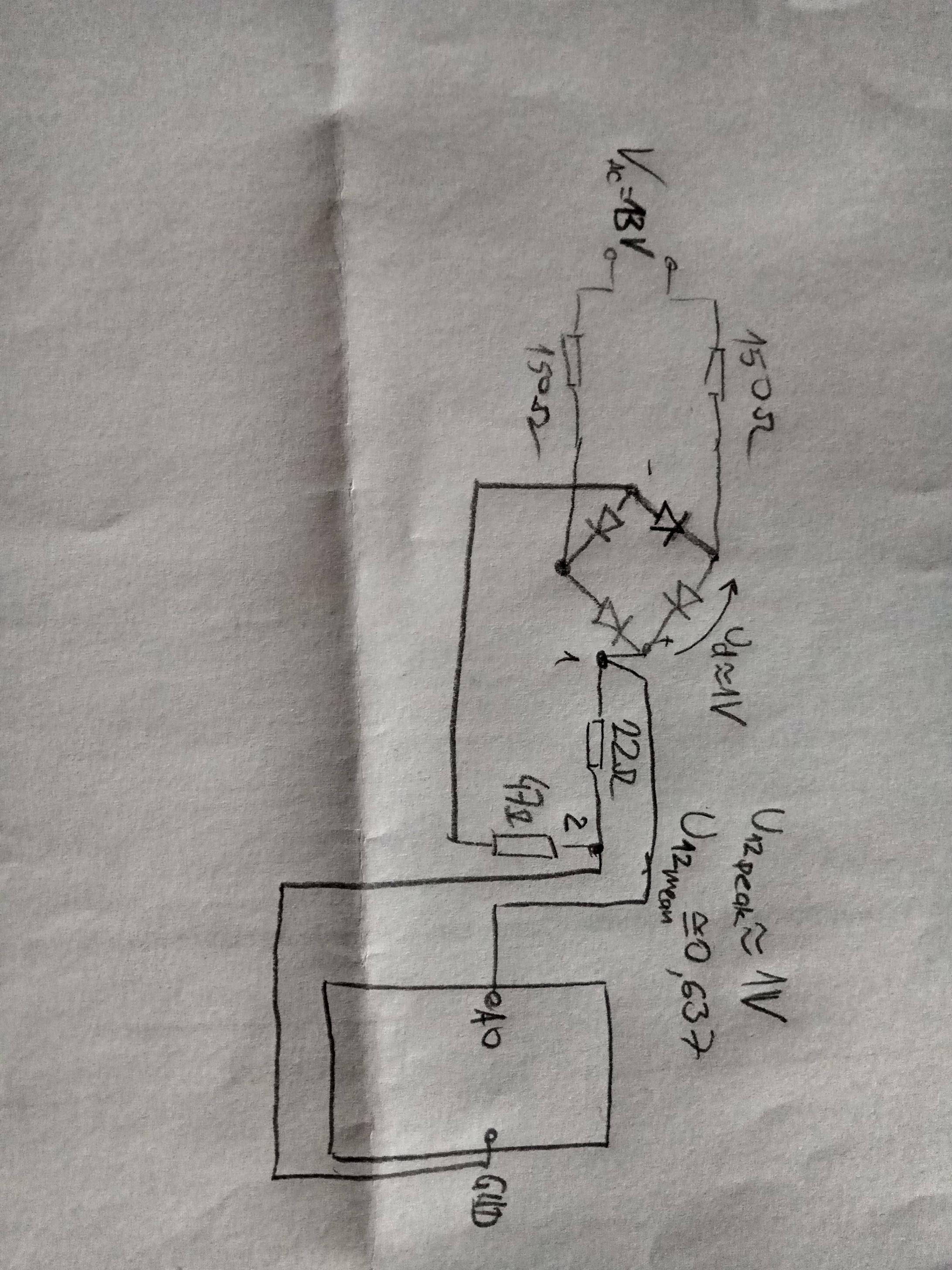
Thank you everbody for the answers. @Smajdalf - thank you for the answer, I didn't marked correctly the values of the resistances on the schematic, my actual idea was to create greater voltage drop before the bridge, as shown bellow.
@wvmarle - I will try that, thank you. I am not sure does my Uno has internal 1.1V adc reference? I've read somewhere that it is possible on Mega. I am going to find it out.
This information was very useful:
DVDdoug:
The Arduino always measures relative to it's ground. And, as you know it can be damaged by negative voltages or voltages greater than +5V, again relative to it's ground.
Before connecting the circuit to my Uno I measured the voltages with a multimeter.
This is the code I wrote:
int i=0;
int wert=0;
unsigned long zeit=0;
unsigned long anfang=0;

void setup() {
  Serial.begin(9600);
  anfang=micros();
}

void loop() {
  while(i<50) {
    wert=analogRead(A0);
    zeit=micros()-anfang;  // gives time relative to the "anfang"
    Serial.print(zeit);
    Serial.print("\t");
    Serial.println(wert);
    delayMicroseconds(195); // I wanted to get samples every 0,2ms,but I
    i++;                    // supposed it needs some time to do the
                            // commands, so instead of 200us I wrote 195us
  }
}
The program schould every cca 200us sample the voltage U12, and send it to Serial. However, something strange happens. It takes samples in irregular intervals, between 19000us and 21000us (so my data are completely random and useless).
Instead to finish its job in 10ms, it takes about 1s to get out of while loop.
I cannot understand what is going on. Does it have something with Serial to do?
Ljiljan:
Does it have something with Serial to do?
Yes. When the Serial buffer is full "Serial.write" waits for it to become free so it becomes unpredictable "delay". You may try to increase the speed of the Serial to some much higher value.
Smajdalf:
Yes. When the Serial buffer is full "Serial.write" waits for it to become free so it becomes unpredictable "delay". You may try to increase the speed of the Serial to some much higher value.
I cannot find which values are allowed? I saw somewhere value of 38400, is there possibility to put some higher value than 38400?
9600 bps means about 1 ms for transmitting 1 character to the Serial console. You're transmitting some 12-15 characters every time that loop runs, that's 12-15 ms there and then. I'd start by setting that to 115200 or so, makes much more sense.
A second problem: the analogRead() call takes about 110 µs to complete, so for doing this every 200 µs delay call is too long.
If you really want samples to be taken every 200 µs the most accurate way is probably to use a timer interrupt. Another way is to use micros() based timing (like Blink Without Delay) to start a new reading every 200 µs, then store the reading in RAM. Of course with just 2048 bytes available the maximum you can store is about 1000 readings, depending on how much RAM for other variables your sktech needs.
That 1,000 readings covers 0.2 seconds, so about 20 half waves assuming you're on 50 Hz AC.
When done sampling, print out the readings to the Serial console.
Ljiljan:
I cannot find which values are allowed? I saw somewhere value of 38400, is there possibility to put some higher value than 38400?
Up to about 1 Mbps. Make sure the value you set to Serial.begin() matches whatever you set in the Serial monitor.
That 38400 you may have seen related to SoftwareSerial. That indeed is far more limited. I'd not normally use it for more than 9600 bps, and in one project I had to reduce it to 2400 bps, or my ESP8266 (running at 80 MHz) would not reliably receive the data... it just had too many other things to do
wvmarle:
9600 bps means about 1 ms for transmitting 1 character to the Serial console. You're transmitting some 12-15 characters every time that loop runs, that's 12-15 ms there and then. I'd start by setting that to 115200 or so, makes much more sense.
A second problem: the analogRead() call takes about 110 µs to complete, so for doing this every 200 µs delay call is too long.
If you really want samples to be taken every 200 µs the most accurate way is probably to use a timer interrupt. Another way is to use micros() based timing (like Blink Without Delay) to start a new reading every 200 µs, then store the reading in RAM. Of course with just 2048 bytes available the maximum you can store is about 1000 readings, depending on how much RAM for other variables your sktech needs.
That 1,000 readings covers 0.2 seconds, so about 20 half waves assuming you're on 50 Hz AC.
When done sampling, print out the readings to the Serial console.
Thank you for these information. This is a good idea to create array wert[] and then later to print it on Serial. I actually need only 50 values in one halfcycle.
Here's my idea:
int i=0;
int wert[50];
unsigned long zeit[50];
unsigned long anfang=0;

void setup() {
  Serial.begin(9600);
  anfang=micros();
}

void loop() {
  while(i<50) {
    wert[i]=analogRead(A0);
    zeit[i]=micros()-anfang;
    delayMicroseconds(80);
    i++;
  }
  for(i=0;i<50;i++) {
    Serial.print(zeit[i]);
    Serial.print("\t\t");
    Serial.println(wert[i]);
  }

}
50 values covers one half cycle, but not a complete one. You'd want at the very least 100 values to be sure to have a single complete "hump" in that data. So why not make that 120 or 150 data points. Data is cheap.
Using micros() based timing should be more accurate, so I was thinking of something like this:
uint8_t count = 0;
uint16_t value[150];
uint32_t time[150];

void loop() {
  if (micros() - lastMeasurement >= 200) {
    lastMeasurement = micros();
    time[count] = micros();
    value[count] = analogRead(A0);
    count++;
  }
  if (count == 150) {
    for (uint8_t i = 0; i < 150; i++) {
      Serial.print(timei]);
      Serial.print('\t');
      Serial.print(value[i]);
    }
    count = 0; // Ready for the next set of measurents.
  }
}
Or, for slightly higher resolution take 200 samples at maximum rate:
uint8_t count = 0;
uint16_t value[200];
uint32_t time[200];

void loop() {
  time[count] = micros();
  value[count] = analogRead(A0);
  count++;
  if (count == 200) {
    for (uint8_t i = 0; i < 150; i++) {
      Serial.print(timei]);
      Serial.print('\t');
      Serial.print(value[i]);
    }
    count = 0; // Ready for the next set of measurents.
  }
}
I'm sorry for answering so late, I wasn't home, and couldn't try.
Thank you everybody for this. I wrote the following code (actually edited the code from Wmarle):
I used 200ohm before rectifier, then voltage divider with 22ohm and 47ohm, and picked the signal between two ends of 22ohm resistor.
int wert[200];
int zeit[200];
int anfang;
int i;
void setup() {
 Serial.begin(9600);

}

void loop() {
  while(analogRead(A0)>2) {}
  anfang=micros();
  for(i=0;i<200;i++) {
    wert[i]=analogRead(A0);
    zeit[i]=micros()-anfang;
  }
  for(i=0;i<200;i++) {
    Serial.print(zeit[i]);
    Serial.print('\t');
    Serial.println(wert[i]);
  }
  delay(15000);
}
This delay(15000); is to have enough time to copy data from Serial into txt file, which I then use in C program (fourier series analyses). I've also got very nice graph in excel as you can see below:
Then I tryed to connect an Elko 100uF between the plus and minus of the rectifier to see what's going on (paying attention to + and - on the capacitor), but something strange started to go on.
Before connecting my Uno I measured the voltage on the 22ohm resistor and the multimeter showed a bit greater value (0,93V instead of 0,86V), what I expected. However when I connected Uno to the computer the Serial monitor didn't show anything. It just stayed empty. Then I disconnected the capacitor and tryed again, and everything was ok. Serial printed values. Then I tryed again with capacitor, and again nothing. Empty Serial monitor. I repeated it all for once more, and again the same. I cannot figure out what is going on. Does it have something to do with the fact that capacitor is elektrolythic? I don't have any other here, I will try tomorrow again with "normal" capacitor.
Just a small edit. I tryed this with several elkos and the last time I plugged out the capacitor (small 4.7uF) while program was working (I know that is not recommended) and the serial monitor suddenly started working normally, printing values.