Well I will admit I am a bit new to the Arduino but I have used the ArduinoMega2560 in the past to program the Attiny85 without issue.
I am attempting to use the Atmega2560 as an ISP for a Atmega328P-PU with its internal clock.
The issue I am having is after burning the bootloader which returns no errors. As soon as I upload any sketch I get:
Binary sketch size: 2,086 bytes (of a 30,720 byte maximum)
C:\Program Files (x86)\Arduino\hardware/tools/avr/bin/avrdude -CC:\Program Files (x86)\Arduino\hardware/tools/avr/etc/avrdude.conf -v -v -v -v -patmega328p -cstk500v1 -P\\.\COM4 -b57600 -D -Uflash:w:C:\Users\Russel\AppData\Local\Temp\build4344446813342895570.tmp\led_to_music_ybr_6_pwm_atmega328.cpp.hex:i

avrdude: Version 5.11, compiled on Sep  2 2011 at 19:38:36
         Copyright (c) 2000-2005 Brian Dean, http://www.bdmicro.com/
         Copyright (c) 2007-2009 Joerg Wunsch

         System wide configuration file is "C:\Program Files (x86)\Arduino\hardware/tools/avr/etc/avrdude.conf"

         Using Port                    : \\.\COM4
         Using Programmer              : stk500v1
         Overriding Baud Rate          : 57600
avrdude: Send: 0 [30]   [20]
avrdude: Send: 0 [30]   [20]
avrdude: Send: 0 [30]   [20]
avrdude: Recv:
avrdude: stk500_getsync(): not in sync: resp=0x00

avrdude done.  Thank you.
This is using the AtMega on bread board boards file and without an external clock.
The pin layout is:
AtMeaga2560 AtMega328
50 18(MISO)
51 17(MOSI)
52 19(SCK)
53 1(RESET)
7(VCC)
8(GND)
I did try adding power to pins 20(AVCC) & 22(AGND) per a different thread and believe that fried the chip. (luckily I have a few)
I have used both a 120ohm resistor and .10uf capacitor in attempt to disable the reset when uploading the sketch. I do not need to do either to burn the bootloader successfully. I also was able to program the Atting85 without disabling the reset on the mega2560.
The Mega 2560 is plugged into a Plugable USB Hub with a separate power supply but I have also tried powering the Mega328 separately.
The ArduinoISP sketch I am using is version 04m3.
The computer is a Windows 7 Home Professional.
I have not yet tried using the 16mghz crystal as an external clock.
I am open to any ideas. I have tried finding something online for a week or so to no avail.
I am attempting to use the Atmega2560 as an ISP for a Atmega328P-PU with its internal clock.
The issue I am having is after burning the bootloader which returns no errors.
Those two are usually mutually exclusive. Which board is selected when you execute Burn Bootloader?
I agree and I am guessing thats why I am unable to find any assistance on the problem online. I select the Arduino as ISP for the programmer and the board is the AtMega328 on Bread board on both the bootloader and uploading the sketch.
dodgeluver85:
...and .10uf capacitor in attempt to disable the reset when uploading the sketch.
Did you mean to write 0.10 uF? If so, you need a bigger capacitor. The Playground page calls for a 10 uF capacitor. I have had good luck with a 47 uF capacitor.
I have tried putting it in both my documents and program files so I have 2 of the same option. I have attempted uploading it as both boards and kept the board selection the same from the boot loader to the upload. The post size is to large so I will post the second boards file after this.
This one is located in C:\Users\User\Documents\Arduino\hardware\attiny
I did mean a .1uf capacitor and I just tried using a 47uf capacitor. I put it from reset (+ capacitor) to ground(-of capacitor) (per http://arduino.cc/en/Tutorial/ArduinoISP) after uploading the ArduinoISP. I then hooked it up and the bootloader which gave me a com error. I then burned the bootloadeer without the capacitor which worked. Then I hooked the capacitor up before clicking upload and I get the same error. Perhaps I am misreading the tutorial is that the correct way to wire it up?
According to my favourite fuse calculator... AVR® Fuse Calculator – The Engbedded Blog ...those settings are a reasonable choice. Once you have everything work, I suggest adding Preserve EEPROM memory through the Chip Erase cycle; [EESAVE=0] and raising the BOD level to Brown-out detection level at VCC=4.3 V; [BODLEVEL=100].
dodgeluver85:
I put it from reset (+ capacitor) to ground(-of capacitor) (per http://arduino.cc/en/Tutorial/ArduinoISP) after uploading the ArduinoISP. ... Then I hooked the capacitor up before clicking upload and I get the same error. Perhaps I am misreading the tutorial is that the correct way to wire it up?
After uploading ArduinoISP to your Mega connect the capacitor as you described and leave it.
I suggest adding series resistors to the three programming lines (MISO, MOSI, SPI) to protect the two processors. Anything between 220 ohms and 1K ohms will work well. A wiring mistake (especially with MISO and MOSI) creates a short-circuit through both processors.
I realized that right after the post I was trying something else and forgot to change it back. I did successfully burn the boot loader with the capacitor attached but received the same error with the sketch.
You are probably correct on not frying it but I am definitely not an expert with this so I disconnected to play it safe.
So to make sure I am understanding you correctly I need to apply 5v to AVCC & VCC as well as ground AGND a GND. Do I need to add additional capacitors to the target?
dodgeluver85:
So to make sure I am understanding you correctly I need to apply 5v to AVCC & VCC as well as ground AGND a GND.
Yes.
Do I need to add additional capacitors to the target?
You need a 0.1 uF capacitor across VCC and GND as close to the processor as possible. You need a 0.1 uF capacitor across AVCC and AGND as close to the processor as possible.
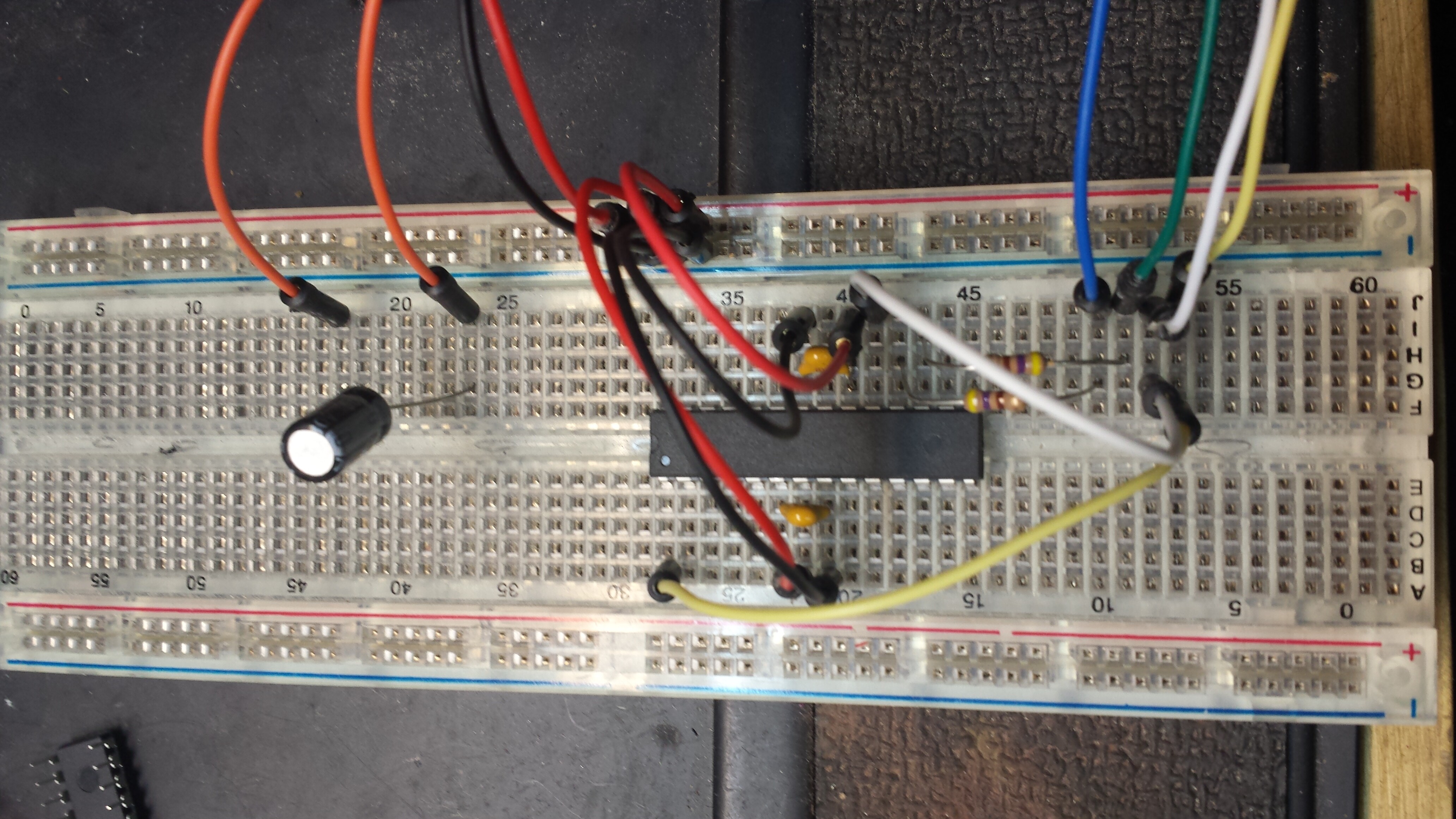
Well I added the resistors in line with the MOSI & MISO but I do not have anything connected to the SPI(SS) so did you mean the SCK? I also added the .1uf capacitor between AVCC & AGND and VCC & GND. I will attached 1 picture of the wiring and will post a second after this. To let you double check my steps:
Select Arduino2560 board in software
Disconnect 47uf capacitor
Upload ArduinoISP version 04m3
Upload is successful
Connect 47uf capacitor from mega2560's reset to GND
Change board to Atmega328 on breadboard
Change programmer to Arduino as ISP
Burn bootloader which is successful
last few lines
just an update..... I tried adding the 16 mhz crystal across pins 9 & 10 with a 22pf capacitor from GND to 9 and a second from GND to 10. The crystal was after the capacitors (closest to the chip. I chose the Arduino Duemilanove w/ Atmega328 as the board and ArduinoISP as programmer (this was after the mega2560 was uploaded with ArduinoISP) It returned the same results. The bootloader was successful and the sketch upload return avrdude: stk500_getsync(): not in sync: resp=0x00.
I just noticed that... I saw the bootlaoder at 19200 and I started looking. do I need to change that in the preferences.txt file then or is there an easier way?