In the MegaCoreX documentation there is a list of available pins for the 4 serial ports in a 4809, the pins shown do not seem to be correct.
The table shows:
Available pin combinations for the 48 pin standard pinout are:
Serial swap(0) or pins(0,1) or swap(1) or pins(4,5)
Comment:
There is no pin 0! If you regard pin 0 as being pin 48 then it almost makes sense as the data sheet shows 48 as 0TxD and 1 as 0RxD
Serial1 swap(0) or pins(14,15) or swap(1) or pins(18,19)
Comment:
Pin 14 is Vdd, 15 GND, not likely to work as as serial port.
Pin 18 is 1XCK, 19 is 1XDIR, not serial pins.
Serial2 swap(0) or pins(34,35) or swap(1) or pins(38,39)
Comment:
Pin 34 is 2TxD, 35 is 2RxD, seems reasonable but given the above I don't quite trust it.
Pins 38 is 2TxD and 39 is 2RxD alternative
Serial3 swap(0) or pins(8,9) or swap(1) or pins(12,13)
Comment:
Pin 8 is 3TxD, 9 3RxD
Pin 12 is 1XCK, 13 is 1XDIR
I'm well impressed with MegaCoreX so far so I am inclined to believe the website and the data sheet are correct and I am just not reading them correctly. Can someone please make sense of this for me?
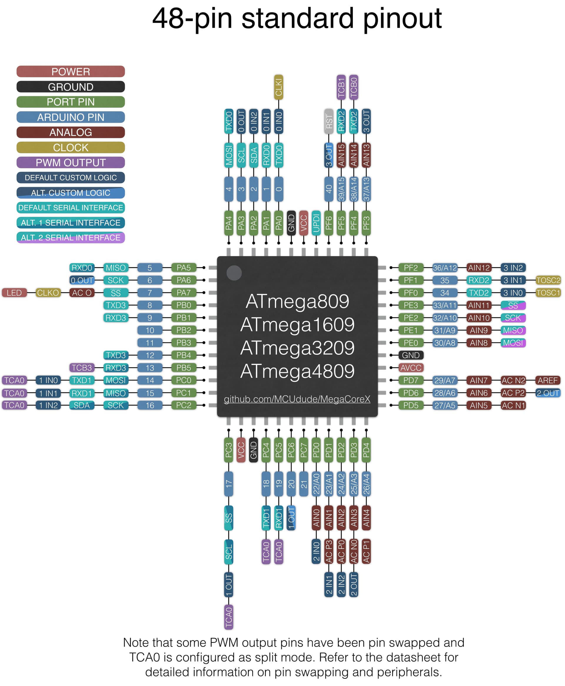
I've not thoroughly checked this all out, but on the main MegaCoreX github page there's a section called Pinout about half way down. There are several package pinouts just below. This is the one for the 48-pin package:
MCUDude has diagrams and pin outs that match:
But the numbering scheme is odd, in that the VCC and GND pins are not counted in the numbering.
It does go anti-clockwise around the chip
I've checked that against the datasheet and they all make sense now.
I never properly looked at that diagram, I have a print out on my desk of the pin out from the data sheet and assumed it was the same. I'd not realised MCUDude had created his own numbering scheme. So my only question, which I guess only he can answer, is: Why???
I can't mark both answers as the solution because the forum software doesn't allow it, so, @markd833 that award goes to you for being first to reply.
That's typical for Arduino-style pin numbering, isn't it?
Start at 0 and only include the useful pins that are brought out on your "board."
(Yeah, I was sort-of hoping for a "chip-based" board type where "Arduino Pin Numbers" would map up exactly with "Chip Pin Numbers", but I think it runs into too many problems surrounding "what do I do if the user uses a pin number with no IO function?")
In the Arduino IDE there is a choice of pinouts to match the particular version of the 4809 (or other micro-controller in the series) you have, the option for the 48 pin device is '48 pin standard', which lead me to believe I was dealing with the standard (manufacturer) pin out.