I tested this again today. Used an external power supply for the Arduino ( USB charger ).
I reconfigured the sketch on the Arduino to only light up the LEDs, I didn't send any power to the MOSFET gate.
With the engine not running, an NPN proximity sensor connected as the sensing device, it works fine. If I start the engine, everything goes crazy. It seems like the sensor is constantly sensing, even though it isn't. This is without the ignition circuit going through the MOSFET.
If I move the board away from the engine it gets a little better, so I guess the engine is causing some interference.
I'm not sure what was happening in my previous tests, but I never connected the sensor before, I just had a wire which I grounded to test when the sensor would have sensed.
I did add a ceramic capacitor between pin D2 and GND right next to pin D2 on my Arduino.
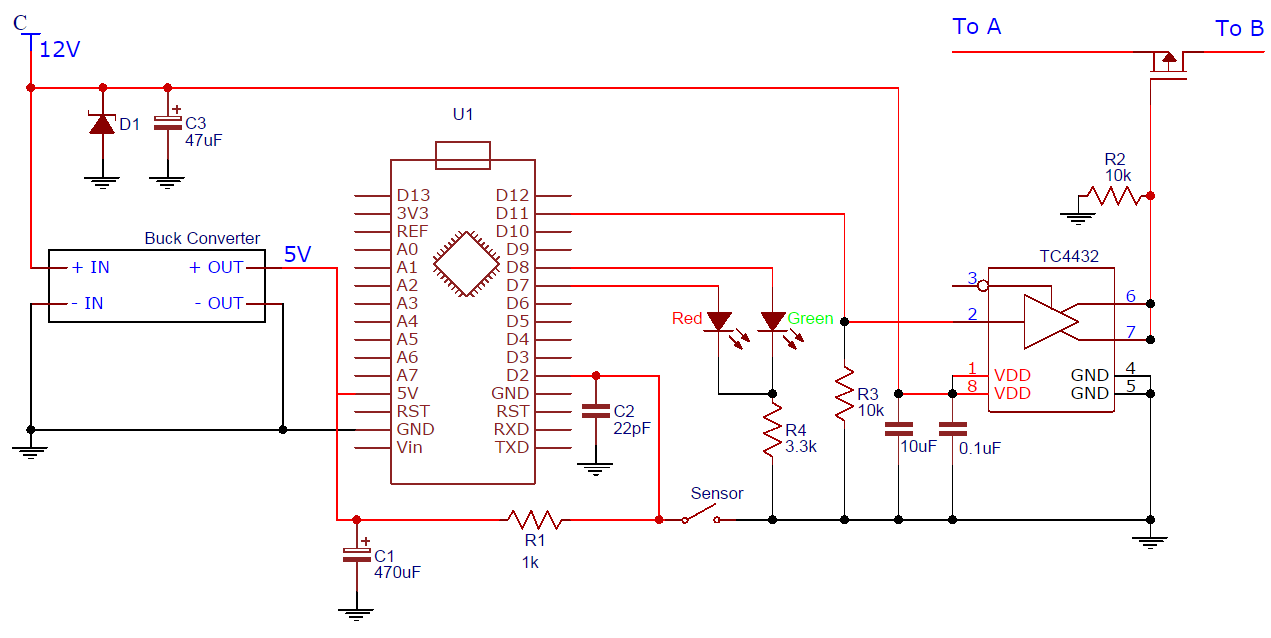
I have added a new schematic, this reflects what I have been testing.
HI there, Since your working on a 12v system I'd like your opinion on something. I have a thread about 12V systems and Arduino. If you would express your thoughts it would be appreciated.
If I move the board away from the engine it gets a little better, so I guess the engine is causing some interference.
If just moving closer and farther away from the running engine changes the response (with the wiring left alone), this suggests that the problem is with radiated EMI, not anything conducted.
Unfortunately, this is a bit out of my depth to give detailed fixes for. The first things I would try would be to enclose the circuitry in a metal box and use shielded twisted pair (from a cannibalized Ethernet cable) for any high-impedance signal connections going out of the box.
Basically, it needs a tin foil hat.
Hopefully someone else is able to chime in to say if my diagnosis and solution of radiated EMI is correct.
Since you brought that up I must admit I had expected the OP was doing that from the beginning since his post is all about false detections. engine emi
I have just realised that my sketch is only debouncing after a sensor event, not for the detection of a sensor event.
I am currently rewriting the sketch. For a 1 ms debounce delay the sensor would need to be low for over 100 iterations of the main loop. I am hoping this change will help significantly.
I have not been testing in a metal enclosure, maybe this is what I need to do next. I was just testing the board near the engine, as I would need to fully insulate it to mount it in a metal box and I want to make sure it is functional first.
I'd just put a few layers of plastic wrap over it, then a layer of aluminum foil over that. I'm not sure if the foil layer would need to be connected to anything (like GND or the bike frame) for maximum shielding effect or if you can just leave it floating, but that might be good enough for a quick test. If everything works with it right up next to the engine, you've got your solution.
Are any of your wires running close (within 6 inches) of ignition coil or wires ? I had and issue on a car where a re routed harness getting to close to a ignition wire caused the ECM to go nuts. Moved the harness and all was well.
sid1202:
Are any of your wires running close (within 6 inches) of ignition coil or wires ? I had and issue on a car where a re routed harness getting to close to a ignition wire caused the ECM to go nuts. Moved the harness and all was well.
Sid
The ignition wires connect directly to my board, they have to as I am interrupting them.
I made a few modifications to the circuit and tested it tonight. Added another electrolytic cap on the sensor pin line, and also increased the capacitance on a ceramic cap right next to the sensor pin.
I have also edited the code to not detect a sensor change until it has been in the new state for more than 1ms.
It was working sweet, no false detections at all!
I need to test this when the engine is doing 16,000 rpm, but that is later. For now I'm just happy it is working.
I would like to thank everyone who helped me out in this thread, especially raschemmel and Jiggy-Ninja.
I have attached a diagram of the current circuit which is working. I will of course update once I have tested this at high rpm values.
rickerman:
The ignition wires connect directly to my board, they have to as I am interrupting them.
We don't have the same definition of "ignition wire" I mean the think wire for the coil to the spark plug. These wires have between 15k to 90k volts going thought them. If your harness is to close to the coil or the ignition wire you will get interference.
I looked at the drawing you posted, look like your controlling the coil leads in order to manage the spark plug firing timing. This is very interesting in deed. Great project!
That's great to hear! Looks like the problem was definitely some kind of EMI, probably radiated from the ignition coils. The two ways to guard against that are blocking it with a metal shield or increasing the amount of energy needed to change the pin's voltage level, which is what you did by adding the capacitor.
Shielding the circuit with metal will probably let you reduce the capacitor so it's not so large. Discharging a 1/2 millifarad capacitor like that might put stress on whatever sensor you're using to trigger the circuit.
Jiggy-Ninja:
That's great to hear! Looks like the problem was definitely some kind of EMI, probably radiated from the ignition coils. The two ways to guard against that are blocking it with a metal shield or increasing the amount of energy needed to change the pin's voltage level, which is what you did by adding the capacitor.
Shielding the circuit with metal will probably let you reduce the capacitor so it's not so large. Discharging a 1/2 millifarad capacitor like that might put stress on whatever sensor you're using to trigger the circuit.
The sensor is an Inductive proximity sensor, capable of 300mA.
sid1202:
We don't have the same definition of "ignition wire" I mean the think wire for the coil to the spark plug. These wires have between 15k to 90k volts going thought them. If your harness is to close to the coil or the ignition wire you will get interference.
I looked at the drawing you posted, look like your controlling the coil leads in order to manage the spark plug firing timing. This is very interesting in deed. Great project!
Sid
Ah, you are taking about HT leads. In this engine it uses "on-plug" coils. So the HT voltage is contained within the coils.
I am not controlling the timing, I am trying to stop the coils from firing for around 60ms. This unloads the transmission and allows a gear to be changed while still at wide open throttle. The proximity sensor will sense when I am about to engage the next gear (This will take some adjusting I think). The sparks will then be cut for 60ms (Adjustable via the sketch) allowing the gear to be selected as the transmission is no longer under load. After 60ms, hopefully the gear is engaged and the sparks will come back on and I will loose as little time as possible changing gear.
have also edited the code to not detect a sensor change until it has been in the new state for more than 1ms.
Let's be clear about something. Unless you post your reasons for choosing 1 mS, we can assume the actual REQUIRED delay could be anything and therefore common sense would dictate that you reduce it incrementally using microseconds until the false detections start to occur to ascertain empirically what the required delay actually is.
There is no logical reason for choosing 1ms. I just thought it was better than no debouncing and is short enough that it wont cause delays.
During testing I reverted my sketch to the one without de-bouncing and it was still working fine, no false detections. So I must conclude that it was one of the capacitors that helped filter out the noise. My only worry now is if there is too much capacitance on that line, is that possible and can it hurt anything?