I assume you have resistors in series with the LEDs..
You already have a pin array (8-12), so why not use it.
Leo..
const byte controlPin[] {2, 3, 4, 5}; // control pins s0-s3
const byte mux1Common = 6;
const byte mux2Common = 7;
const byte numPins = 5;
const byte pins[] {8, 9, 10, 11, 12}; // output pins to train controller
byte number; // holds number of the button pressed

void setup() {
  for (byte i = 0; i < 4; i++) pinMode(controlPin[i], OUTPUT); // four control pins
  for (byte i = 0; i < 5; i++) pinMode(pins[i], OUTPUT); // five output pins
  Serial.begin(9600);
}

void loop() {
  for (byte i = 0; i < 16; i++) { // channels
    for (byte s = 0; s < 4; s++) digitalWrite (controlPin[s], bitRead(i, s)); // set four control pins
    if (!digitalRead(mux1Common)) number = i; // any on mux#1 button pressed
    else if (!digitalRead(mux2Common)) number = i + 16; // any on mux#2 button pressed
    else number = 0; // nothing pressed
    for (byte x = 0; x < 5; x++)digitalWrite(pins[x], bitRead(number, x));
    delay(250);
  }
}
The program worked although I had to remove the delay as it caused the LEDS to flash brightly momentarly but turn off for a couple of seconds. with the delay removed I am still getting low voltage 1's. I will get an oscilloscope tomorrow an see what the pulse witdths I am getting.
Paul
I do have pullups on all the mux inputs.
It seems like more a timing problem in the Arduino. The fact that it worked fine before I tried resetting back to 0000 when the button is released also with the delay (250) it flashed brightly. This may be enough for my requirements as I will only be pressing the buttons briefly.
I did a bit of experimenting with the delay and if I took it to 1000 it flashed on for a second but then stayed off for about 12 secs. I also took it to 100 and it flashes on but still is off for about 4 secs.
Paul
Ofcourse it will behave like that since 99% of the time it is executing delay(); .
Try this one
const byte controlPin[] {2, 3, 4, 5}; // control pins s0-s3
const byte mux1Common = 6;
const byte mux2Common = 7;
const byte numPins = 5;
const byte pins[] {8, 9, 10, 11, 12}; // output pins to train controller
byte number; // holds number of the button pressed

void setup() {
  for (byte i = 0; i < 4; i++) pinMode(controlPin[i], OUTPUT); // four control pins
  for (byte i = 0; i < 5; i++) pinMode(pins[i], OUTPUT); // five output pins
  Serial.begin(9600);
}

void loop() {
  for (byte i = 0; i < 16; i++) { // channels
    for (byte s = 0; s < 4; s++) digitalWrite (controlPin[s], bitRead(i, s)); // set four control pins
    if (!digitalRead(mux1Common)) number = i; // any on mux#1 button pressed
    else if (!digitalRead(mux2Common)) number = i + 16; // any on mux#2 button pressed
    else number = 0; // nothing pressed
    for (byte x = 0; x < 5; x++)digitalWrite(pins[x], bitRead(number, x));
if (number!=0){delay(250);}

  }
}
Thanks for the input but the Arduino didn't like it. The correct codes are still displayed and brightly but when the button is released it cycles through 0000....1111
Can't see why the code isn't working as it should, even without the delay call.
I would like to see a picture of the build/setup of the 74HC4067 part.
Didn't have 4067 chips anymore, but I will order some to try myself.
Leo..
Edit: I assume you do have pull up resistors ( between mux pins and 5volt), with the switches between mux pins and ground. Not pull down resistors, with the switches to VCC.
Because then the outputs will count binary from 0 to 15,
Leo, The pullups are all to Vcc. I had read somewhere that it was better to use external ones but that may have been misinformation.
The last sketch that you posted will suffice for what I require as it pulses as soon as the button is pressed then resets to 0000 and that is all I require to feed to the train controller.
My test setup. A bit untidy but it works. The green wire on the RHS is my switch to select input.
I forgot to mention that I am testing with a Uno as my system won't talk to either of my Nanos at present despite changing com ports as suggested and uninstalling Arduino and reinstalling the latest.
avrdude: ser_open(): can't set com-state for "\.\COM5"
Failed uploading: uploading error: exit status 1
I am old fashioned and usually use real resistors. Here's a case where I would def feel better (!) with real relatively hard pull-ups.
And though I did point out that one would suffice, at the input pin, I'd probably still go to the trouble and expense of pull-ups per switch.And as @Wawa nites, you have them aready so I'd just leave well en;ugh alone.
The internal pull-ups work well but are relatively weak.
Leo, Sorry for the delay as I have only just got back to it.
I have been experementing with different delays and seeing what comes up on the oscilloscope I have manages a photo without delay of pin 0 but cannot capture with delay as my phone camera is not fast enough.
I have managed to upload to a Nano with a mini PC with the old boot loader.
With a 250ms delay I get a 200mS pulse at 5V
with a 1000ms delay a 1 sec pulse at 5v.
I am also getting a delay between pushing the button and an output. This could be that the Nano is a bit slow processing the data. I may have to go back to the Uno but was trying to save space.
I was wondering whether it is possible to latch the output as the current delay seems to increase the down time markedly.
Paul
I have ordered a few mux boards, but they take a few days to arrive.
Confused. Please explain exactly what you want to happen.
Do you want the output to stay as short as possible, independent on how long you push a button, and then return to zero. Or do you want the output to stay for a fixed amount of time, even with a very short button push.
Leo..
I would be happy if it stayed on for as long as the button is pressed. At present there is a delay before getting an output and if the button is released there is no output. The larger the delay the longer before the initial output but if the delay is too short it cycles quickly through the loopl;
Instant output on button press, and instant return to zero when released is how I tried to code it, but maybe there are Gremlins at work. Can you wait a few days, until my parts have arrived.
Leo..
#define select0Pin 2 // Select 0
#define select1Pin 3 // Select 1
#define select2Pin 4 // Select 2
#define select3Pin 5 // Select 3
#define commonInputAPin 6 // Common Input
#define commonInputBPin 7 // Common Input
#define zoneAPin 8 // Zone A: Sensor 0 - 7
#define zoneBPin 9 // Zone B: Sensor 8 - 15
#define zoneCPin 10 // Zone C: Sensor 16 - 23
#define zoneDPin 11 // Zone D: Sensor 24 - 31
#define commonZonePin 12 // Common
const uint8_t selectPins[] = {select0Pin, select1Pin, select2Pin, select3Pin}; // Select Pin Array
const uint8_t commonInputPins[] = {commonInputAPin, commonInputBPin}; // Common Input Array
const uint8_t numberOfSelects = 4; // Number Of Selection Pin
const uint8_t numberOfChannels = 16; // Number Of Channels per Multiplexer/Demultiplexer
const uint8_t numberOfMultiplexers = 2; // Number Of Multiplexer/Demultiplexer
// Declare Valiable for Example
const uint8_t zonePins[] = {zoneAPin, zoneBPin, zoneCPin, zoneDPin}; // Zone Pin Array
const uint8_t numberOfZones = 4; // Number of Zones
const uint8_t size = 8; // Number of Sensor per group
bool zoneStates[numberOfZones]; // Zone State
// Input State
typedef struct {
bool input; // Input State
bool state; // Output State
unsigned long startTime; // Debounce State Time
} SensorState;
const uint8_t numberOfSensors = numberOfMultiplexers * numberOfChannels;
SensorState inputs[numberOfSensors]; // Declare Debounce Input with State;
const unsigned long debounceTime = 10UL; // Declare Debounce Time in milliseconds
// Declare Variable for Blink
#define blinkDelayTime 500UL
bool blink; // Blink State
unsigned long startTime; // Blink Start Time
void InputMultiplexer(); // Declare Input Multiplexer Function
void SelectChannel(uint8_t channel); // Declare Select Channel Function
void InputDebounce(bool input, uint8_t index); // Declare Input Debounce Function
void Process(); // Declare Process Function
void Blink(); // Declare Blink Function
bool V1ooN(uint8_t startChannel, uint8_t count); // Voting 1 out of N
void setup() {
Serial.begin(115200);
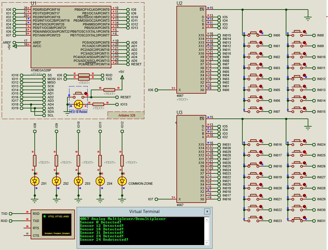
Serial.println("4067 Analog Multiplexer/Demultiplexer");
for (uint8_t index = 0; index < numberOfSelects; index++) {
pinMode(selectPins[index], OUTPUT); // Set selectPins Pin Mode
}
for (uint8_t index = 0; index < numberOfMultiplexers; index++) {
pinMode(commonInputPins[index], INPUT_PULLUP); // Set Common Input Pin Mode
}
for (uint8_t index = 0; index < numberOfZones; index++) {
pinMode(zonePins[index], OUTPUT); // Set Zone Pin Mode
}
pinMode(commonZonePin, OUTPUT); // Set Common Zone Pin Mode
pinMode(LED_BUILTIN, OUTPUT); // Set LED_BUILTIN Pin Mode
blink = false; // Initial Blink State
startTime = millis(); // Set a start time
}
void loop() {
InputMultiplexer(); // Call Input Multiplexer Funciton
Process(); // Call Process Funciton
Blink(); // Call Blink Funciton
}
void InputMultiplexer() {
for (uint8_t index = 0; index < numberOfChannels; index++) {
SelectChannel(index); // Select Channel
for (uint8_t multiplexer = 0; multiplexer < numberOfMultiplexers; multiplexer++) {
bool state = !digitalRead(commonInputPins[multiplexer]); // Read Input
uint8_t sensor = index + multiplexer * numberOfChannels; // Calculate Sensor Number
InputDebounce(state, sensor); // Debounce Input
}
}
}
void SelectChannel(uint8_t channel) {
for (uint8_t channelIndex = 0; channelIndex < numberOfSelects; channelIndex++) {
bool select = bitRead(channel, channelIndex); // Read Bit State
digitalWrite(selectPins[channelIndex], select); // Write Select State
}
}
void InputDebounce(bool input, uint8_t index) {
if (input != inputs[index].input) { // Compare if State Changed
inputs[index].startTime = millis(); // Set Start Time with current millis
}
inputs[index].input = input; // Store current input to input state
if (inputs[index].state == input) return; // Return if the state does not change
unsigned long elapsed = millis() - inputs[index].startTime; // Calculate elapsed time
if (elapsed < debounceTime) return; // Return if debounce does not complete
inputs[index].state = input; // Store current input to input state
if (input) Serial.println("Sensor " + String(index) + " Detected!");
if (!input) Serial.println("Sensor " + String(index) + " Undetected!");
}
void Process() {
// TODO: Control
// BEGIN: EXAMPLE
bool common = false;
for (uint8_t zone = 0; zone < numberOfZones; zone++) {
uint8_t start = zone * size;
zoneStates[zone] = V1ooN(start, size); // Reset Zone state
digitalWrite(zonePins[zone], zoneStates[zone]); // Write Zone state to Zone LED
common |= zoneStates[zone]; // 1 out of 4
}
digitalWrite(commonZonePin, common); // Write Common State to LED
// END: EXAMPLE
}
bool V1ooN(uint8_t startChannel, uint8_t count) {
uint8_t endChannel = startChannel + count; // Calculate end channel
for (uint8_t index = startChannel; index < endChannel; index++) {
if (inputs[index].state) return true; // Return if one out of n TRUE;
}
return false;
}
void Blink() {
unsigned elapsedTime = millis() - startTime;
if (elapsedTime < blinkDelayTime) return;
startTime = millis(); // Set A New Start Time
blink = !blink; // Togle Blink State
digitalWrite(LED_BUILTIN, blink); // Write Blink State to LED
}
microbeaut I tried your code but unfortunately it does not decode.
If buttons 0 -7 pressed output only from pin8
If buttons 8 -15 pressed output only from pin9
If buttons 16 -23 pressed output only from pin10
If buttons 24 -31 pressed output only from pin11
no output from pin 12.
This is pressing one button at a time