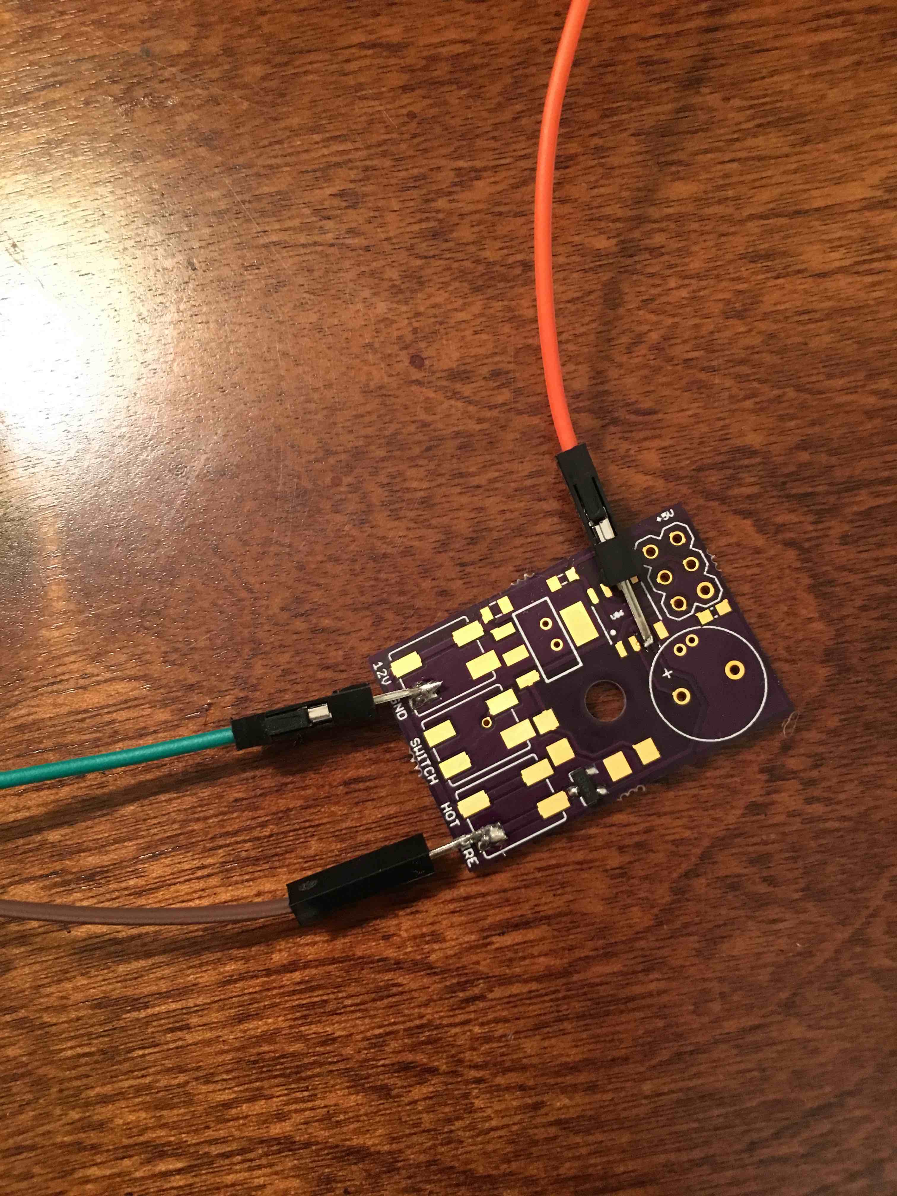
I'm at a loss as to the problem, but I'm trying to use this SMD N channel Mosfet as a small switch. I actually have 2 different custom boards I've made with it on, and neither are working, So I populated on of my boards with the bare minimum to test it, and it's not working. Seems like it's on all the time, whether I turn Digital pin 4 on or off. Here's photos of the schematic, the board layout, and even one of the actual real life board. I don't think I have the source/drain/gate hooked up wrong, do I?
Thanks!
PS. The board has a 5 volt regulator on it for the ATtiny85. I tested the ATtiny85 by have it blink a different pin on and off, and watching it with my meter, and it was working. So I know the ATtiny85 is working. But when I had it blink D4 on and off every second, (that's that pin connected to the gate of the MOSFET), it was always on according to my meter.
I used a 5ohm 25watt resistor.
Ammeter showed about 2 amps current flow - all the time. Regardless of the digital Pin state
According to the data sheet at three votes it can handle 4+ amps.
My end result will be a DC gearmotor the drawls about 300 mill amps
If you've got an LED so you can see the gate is switching.... The MOSFET is backwards, or it's shorted/blown, or it's the wrong part. I'd guess you've got the drain & source reversed. (I didn't check the datasheet or your board layout.)
I used a 5ohm 25watt resistor.
Ammeter showed about 2 amps current flow - all the time
Next time, I'd suggest starting with a "lighter" load. Maybe an LED with a few-hundred Ohm series resistor... Something that can't burn anything up even if it (or something else) is wired wrong. When that works, you can add a heaver load or the actual load. And, you can optionally leave the LED in the circuit so you can if it still works with the real load...
No I have the pin mode set.
I’m going to try a new bare PCBoard, and only populate the MOSFET and three jumper wires. I’ll connect the source to ground, the gate to a 5 V supply from my Uno (I’ll tie the grounds together from My Uno and my 12 V power supply ) and the drain I’ll connect to The ground of a small gear motor powered by 12 volts on the positive side of the gear motor
Set a van when I connect or on connect the gate from the 5 V supply that should turn the motor on or off right? Don’t go away I’ll try this and be back in 10 minutes!
OK, with the bare bones test, I got it working. I discovered that if the gate is left open, the MOSFET will kick on. It'd put off if I grounded it. But just a finger touch on the lead would start the motor running again.
Also, a current draw of 2.1 amps (that was using a 5ohm, 25 watt power resistor as the load), the MOSFET would slowly heat up, too hot to touch. I need to find a slightly large package surface mount MOSFET that'll work with low voltage TTL.
SouthernAtHeart:
So I seems I need a pull down resistor on the gate to keep it off. Would 10K be a good selection?
But surely only in your limited (barebones) test environment without the MCU. A digital pin on an ATTiny85 should be close to the rails ( 0 Volts when off and 5 Volts when On ) so ensure that the mosfet is either fully on or fully off.
Edit.
Include your test sketch in the post anyway.
SouthernAtHeart:
So I seems I need a pull down resistor on the gate to keep it off. Would 10K be a good selection?
A MOSFET should always have a pull-down resistor on the gate. Otherwise all kinds of weird things happen - the worst being a partly opened gate and a burned-up MOSFET. The ATtiny will always start up with pins set to INPUT so until your code kicks in and sets it to OUTPUT, LOW the gate level is undefined.
10k is a common value for pull-down. if you're battery powered you want to increase this, usually 1M or even higher resistance will work just fine and limit current leakage when your pin is HIGH.
SouthernAtHeart:
OK, with the bare bones test, I got it working. I discovered that if the gate is left open, the MOSFET will kick on. It'd put off if I grounded it. But just a finger touch on the lead would start the motor running again.
Yep.... something is very wrong there, that's for sure. If it's all wired up correctly, and if you've manually grounded the gate of mosfet.... then the mosfet should not be supplying power to the load (ie. the motor).
Better make sure your jumper leads etc are all 'good', and to double-check that you have indeed wired up the mosfet correctly -ie. absolutely sure the pins are all the correct ones, and the the ground (or grounds) are indeed grounds.
SouthernAtHeart:
I used a 5ohm 25watt resistor.
Ammeter showed about 2 amps current flow - all the time. Regardless of the digital Pin state
According to the data sheet at three votes it can handle 4+ amps.
My end result will be a DC gearmotor the drawls about 300 mill amps
At 3 volts drive it can handle 2A at 25 centigrade, (I presume assuming good PCB thermals, which
is doubtful on that breakout).
If its on all the time you may have fried it. Small MOSFETs are very static sensitive, they have no protection
diodes. Just touching the gate electrode is enough to destroy a MOSFET.