I put an output for a led on digital pin 5, I need to upload a program for it to be able to interact with it.
But I don't have pin buses that give me access to the serial outputs of the Atmega328PB, so I wanted to do this through the SPI.
The led L of my arduino UNO is blinking a lot, and the LED that was to light up by the Atmega is not lighting up.
https://www.youtube.com/watch?v=1HA1is4I9R0
avrdude: Version 7.1-arduino.1
         Copyright the AVRDUDE authors;
         see https://github.com/avrdudes/avrdude/blob/main/AUTHORS

         System wide configuration file is C:\Users\Matheus Markies\AppData\Local\Arduino15\packages\MiniCore\hardware\avr\2.2.1\avrdude.conf

         Using Port                    : COM4
         Using Programmer              : arduino
         Overriding Baud Rate          : 115200
         AVR Part                      : ATmega328PB
         Chip Erase delay              : 10500 us
         PAGEL                         : PD7
         BS2                           : PC2
         RESET disposition             : possible i/o
         RETRY pulse                   : SCK
         Serial program mode           : yes
         Parallel program mode         : yes
         Timeout                       : 200
         StabDelay                     : 100
         CmdexeDelay                   : 25
         SyncLoops                     : 32
         PollIndex                     : 3
         PollValue                     : 0x53
         Memory Detail                 :

                                           Block Poll               Page                       Polled
           Memory Type Alias    Mode Delay Size  Indx Paged  Size   Size #Pages MinW  MaxW   ReadBack
           ----------- -------- ---- ----- ----- ---- ------ ------ ---- ------ ----- ----- ---------
           eeprom                 65    20     4    0 no       1024    4      0  3600  3600 0xff 0xff
           flash                  65     6   128    0 yes     32768  128    256  4500  4500 0xff 0xff
           lfuse                   0     0     0    0 no          1    1      0  4500  4500 0x00 0x00
           hfuse                   0     0     0    0 no          1    1      0  4500  4500 0x00 0x00
           efuse                   0     0     0    0 no          1    1      0  4500  4500 0x00 0x00
           lock                    0     0     0    0 no          1    1      0  4500  4500 0x00 0x00
           signature               0     0     0    0 no          3    1      0     0     0 0x00 0x00
           calibration             0     0     0    0 no          1    1      0     0     0 0x00 0x00

         Programmer Type : Arduino
         Description     : Arduino for bootloader using STK500 v1 protocol
         Hardware Version: 3
         Firmware Version: 4.4

avrdude: AVR device initialized and ready to accept instructions
avrdude: device signature = 0x1e950f (probably m328pb)
avrdude: reading input file C:\Users\Matheus Markies\AppData\Local\Temp\arduino\sketches\DCF8D2F989BFD387A87EBD92A1E64F93/TurnOnTest.ino.hex for flash
         with 1232 bytes in 1 section within [0, 0x4cf]
         using 10 pages and 48 pad bytes
avrdude: writing 1232 bytes flash ...

Writing | ################################################## | 100% 0.22s

avrdude: 1232 bytes of flash written

avrdude done.  Thank you.
const int ledPin = 5;

void setup() {
  pinMode(ledPin, OUTPUT);
}

void loop() {
  digitalWrite(ledPin, HIGH);
  delay(1000);

  digitalWrite(ledPin, LOW);
  delay(1000);
}
Hi,
Is there any reason why, apart from size, you did not just put some headers on your PCB and plug a Nano into it?
Tom... ![]()
![]()
![]()
![]()
This PCB is designed for a device that includes a set of sensors to measure vibration, temperature, and current in industrial electric motors. Initially the prototype used an Arduino Nano, but now the PCB has been created to fit inside a box with all the necessary chips integrated in one piece. However, we are experiencing problems with data recording due to the lack of pins for serial and SPI communication.
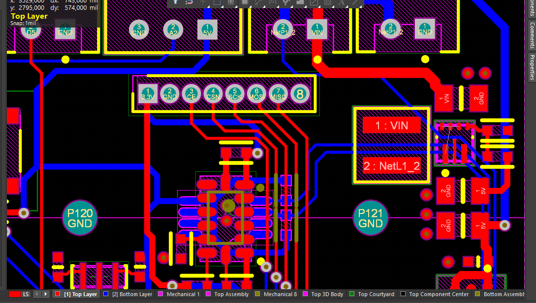
We considered using the nRF24L01 connections, but the SPI pins were incorrectly connected to the MISO1, MOSI1 and SCK1 pins, instead of their corresponding 0 pins. Also, the bus intended for serial communication was connected to the MOSI0 and MISO0 pins, instead of the intended RX and TX pins. These design errors made it into the final PCB and now we need to find a solution to load the codes without losing the lot of parts.
The video is not really helpful, is Uno connected to your board, even after you uploaded the sketch?
Your schematic doesn't seem to match what is shown in the picture of your board,
So it's difficult to know if what you are doing is right or wrong?
I see from the video you needed to do some hacking for the SCK and RESET connections.
Hi, @Matheus_Markies
Can you post some jpg EXPORT images of your PCB from the CAD please.
Thanks.. Tom.. ![]()
![]()
![]()
![]()
1 Like
Files and images:


Gerber:
Gerber_v3 (1).zip (144.1 KB)
AltiumDesigner:
Schematic:
MSPM-1.pdf (289.5 KB)
MSPM_ADXL.pdf (466.3 KB)
BOM:
T-1P6W476544A-5sets-MSPM_ADXL_BOM+(1)(2023-03-03).pdf (76.1 KB)
Yes, the correct is to disconnect?
I confused as to what you want to do.
The whole point of burning a bootloader is so that you won't need an external ISP programming device.
If you are going to use the Arduino as ISP then there is no need for a bootloader. Is that your intent?
I don't need a bootloader for atmega chips on a dedicated board? Sorry, to tell you the truth I never worked with this.
I need to write code on this chip, if it can be done without a bootloader just with the Arduino ISP even better.
But when I upload a code to it nothing happens.
Not sure what pin 5 would be. But you can use SCK1 instead of 5, hook up your LED plus resistor to the NRF's SCK pin and check if that works.
const int ledPin = SCK1;
I`ve spotted something suspicious on the schematic, the caps around crystal , (C1 and C2) should be around 22pF not 10uF.
1 Like
Another eagle-eye ![]()
So use "uploading using programmer" to upload your TurnOnTest.ino sketch.
Disconnect the reset wire then press the reset button on your custom PCB.
If you have the LED polarity correct, it should blink.
If not, then I'm out of suggestions.
1 Like
I don't know what value to place on the schematic given in post #1. According to post #8 the schematic does not relate to the current board design.
Finally I got it working, I was sending the sketch to the arduino UNO instead of the Atmega328pb since the Arduino IDE in the PT/BR version the shortcuts CTRL + U (Upload) and CTRL +SHIFT+ U (Upload using programmer) are with the same name...
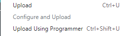

I didn't see that these shortcuts existed, so I always clicked on the wrong menu... ![]()
The module is still responding in a strange way, the delay of the led is for 2s but it is blinking at a very high frequency, but this is another problem.
Thanks!
You need to select 16Mz external clock clock when burning the bootloader
I don't know if I can ask in this same post again but, the led flashes strange and an hour the circuit burns. ![]()
I tried to make it send messages via serial, it should send every 2 seconds but I just get the messages when I click the reset button.
Do you mean like in real hot with smoke