Once you have the multiplexing function set up, the game is then played and the display[] info updated as needed.
jasmine2501:
Wow, this is pretty complicated. I would have done this with a string of WS2812 RGB addressable LEDs, arranged in a matrix shape. That would eliminate the complexity of lighting the LEDs yourself and allow you to focus on the game-play.Will this game also have buttons associated with each LED? This is a great idea!
Yes I have made a button pad and 4 other buttons. My thinking was I would have something like a left, right, up, down, A, B, start, and select.
CrossRoads:
Once you have the multiplexing function set up, the game is then played and the display[] info updated as needed.
Okay, makes sense. Do you have a code example of something like "all 25 blue LED's on for 3 seconds" or point me to a tutorial?
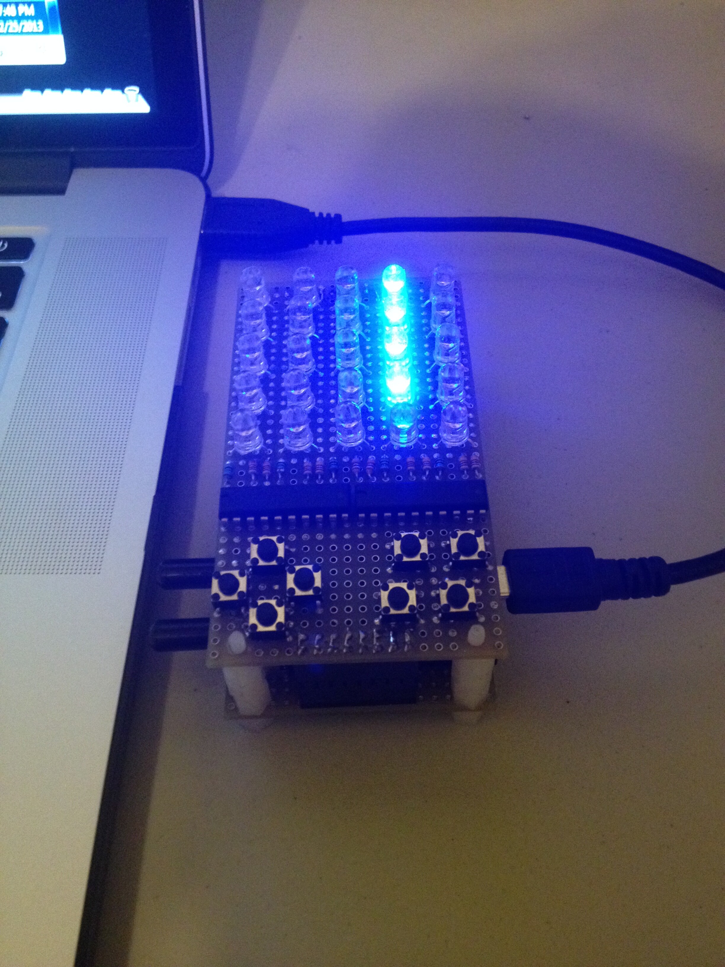
Is all of 1 color on for now?
The idea is that you would change this part when you wanted to show something else:
  // time to change the display?:
  int elapsedMicros2 = currentMicros - previousMicros2;
  if (elapsedMicros2 >= displayTime){ // displayTime = 1000000UL, 1 second ?
    previousMicros2 = previousMicros2 + displayTime;
    // write the code to change display[] for the next color to be on
  } // end time check
So you could count how many times 1 second had elapsed, and after 3 change the data in display[].
  // time to change the display?:
  int elapsedMicros2 = currentMicros - previousMicros2;
  if (elapsedMicros2 >= displayTime){ // displayTime = 1000000UL, 1 second ?
    previousMicros2 = previousMicros2 + displayTime;
testCount = testCount +1;
if (testCount ==3){
display[] = {  // '1' at a location results in an On LED, will send 1 column at a time
  0x00, // column 0, Red, upper 3 bits bit connected to anything: also 0b00011111
  0x1f, // column 0, Green
  0x00, // column 0, Blue

  0x00, // column 1
  0x1f,
  0x00,

  0x00, // column 2
  0x1f,
  0x00,

  0x00, // column 3
  0x1f,
  0x00,

  0x00, //column 4
  0x1f,
  0x00,
};
}
if (testCount == 6){
display[] = {  // '1' at a location results in an On LED, will send 1 column at a time
  0x00, // column 0, Red, upper 3 bits bit connected to anything: also 0b00011111
  0x00, // column 0, Green
  0x1f, // column 0, Blue

  0x00, // column 1
  0x00,
  0x1f,

  0x00, // column 2
  0x00,
  0x1f,

  0x00, // column 3
  0x00,
  0x1f,

  0x00, //column 4
  0x00,
  0x1f,
};
}
if (testCount == 9){
testCount = 0;
display[] = {  // '1' at a location results in an On LED, will send 1 column at a time
  0x1f, // column 0, Red, upper 3 bits bit connected to anything: also 0b00011111
  0x00, // column 0, Green
  0x00, // column 0, Blue

  0x1f, // column 1
  0x00,
  0x00,

  0x1f, // column 2
  0x00,
  0x00,

  0x1f, // column 3
  0x00,
  0x00,

  0x01f, //column 4
  0x00,
  0x00,
};
}
  } // end time check
They flicker on in every color when I turn the device on. But after that there is nothing.
Also, should "display[]" be "byte display[]" ?
I'm getting the following errors: expected primary-expression before ']' token
expected primary-expression before '{' token
expected `;' before '{' token
no, display[] is already declared as byte in the pre-setup area.
The other is a typo somewhere, figure it out. Maybe the variables not declared in pre-setup area.
CrossRoads:
no, display[] is already declared as byte in the pre-setup area.The other is a typo somewhere, figure it out. Maybe the variables not declared in pre-setup area.
I tried different things and couldn't find any typo. The Arduino editor highlights each:
"display[] = { // '1' at a location results in an On LED, will send 1 column at a time"
#include <SPI.h>

int cathodeSS = 0;
int anodeSS = 0;
int columnCount = 5;
int testCount = 6;    //Turn on Green = 3, Turn on Blue = 6, Turn on Red = 9

long previousMicros1 = 0;
long columnTime = 2200UL;
long previousMicros2 = 0;
long displayTime = 1000000UL;
unsigned long elapsedMicros1;
unsigned long elapsedMicros2;
unsigned long currentMicros;

void setup() {
  pinMode(cathodeSS,OUTPUT);
  pinMode(anodeSS,OUTPUT);
  digitalWrite(cathodeSS,HIGH);
  digitalWrite(anodeSS,HIGH);

  Serial.begin(9600);
  SPI.begin();
}


// set up a couple of arrays:
byte display[] = {  // '1' at a location results in an On LED, will send 1 column at a time
  0x1f, // column 0, Red, upper 3 bits bit connected to anything: also 0b00011111
  0x00, // column 0, Green
  0x00, // column 0, Blue

  0x1f, // column 1
  0x00,
  0x00,

  0x1f, // column 2
  0x00,
  0x00,

  0x1f, // column 3
  0x00,
  0x00,

  0x1f, //column 4
  0x00,
  0x00,
};

// these may need swapping end for end, depends on how shift registers are wired
byte cathodes[] = {
  //will send in pairs, column with a 1 will be turned on
  0x80, 0x00,  // column 0
  0x40, 0x00,  // 1
  0x20, 0x00,  // 2
  0x10, 0x00,  // 3
  0x08, 0x00,  // 4
  0x04, 0x00,  // 5
  0x02, 0x00,  // 6
  0x01, 0x00,  // 7
  0x00, 0x80,  // 8
  0x00, 0x40,  // 9
  0x00, 0x20,  // 10
  0x00, 0x10,  // 11
  0x00, 0x08,  // 12
  0x00, 0x04,  // 13
  0x00, 0x02,  // 14
  // 0x00, 0x01 not used
};

// then create the code in loop that will update the shift registers every 2200 microseconds (2.2mS):
void loop(){
  //Matrix Control:
  currentMicros = micros();
  elapsedMicros1 = currentMicros - previousMicros1;
  if (elapsedMicros1 >= columnTime){ // columnTime = 2200UL (1/(15 x 2.2mS) = 30 Hz
    previousMicros1 = previousMicros1 + columnTime;
    // turn off cathodes
    digitalWrite (cathodeSS, LOW); // I would use direct port manipulation vs digitalWrite, way faster
    SPI.transfer(0);
    SPI.transfer(0);
    digitalWrite (cathodeSS, HIGH);
    // shift out next anode data
    columnCount = columnCount +1;
    if (columnCount == 15){
      columnCount = 0;
    } // reset after column 14
    digitalWrite (anodeSS, HIGH); // think '164  needs High on DS to allow 2nd DS to be used
    SPI.transfer(display[columnCount]);
    digitalWrite (anodeSS, LOW);
    // now turn on next cathode
    digitalWrite (cathodeSS, LOW);
    SPI.transfer(cathodes[(columnCount *2)+0]);
    SPI.transfer(cathodes[(columnCount *2)+1]);
    digitalWrite (cathodeSS, HIGH);
  } // end time check
  // time to change the display?:
  elapsedMicros2 = currentMicros - previousMicros2;
  if (elapsedMicros2 >= displayTime){ // displayTime = 1000000UL, 1 second ?
    previousMicros2 = previousMicros2 + displayTime;
testCount = testCount +1;
if (testCount ==3){
display[] = {  // '1' at a location results in an On LED, will send 1 column at a time
  0x00, // column 0, Red, upper 3 bits bit connected to anything: also 0b00011111
  0x1f, // column 0, Green
  0x00, // column 0, Blue

  0x00, // column 1
  0x1f,
  0x00,

  0x00, // column 2
  0x1f,
  0x00,

  0x00, // column 3
  0x1f,
  0x00,

  0x00, //column 4
  0x1f,
  0x00,
};
}
if (testCount == 6){
display[] = {  // '1' at a location results in an On LED, will send 1 column at a time
  0x00, // column 0, Red, upper 3 bits bit connected to anything: also 0b00011111
  0x00, // column 0, Green
  0x1f, // column 0, Blue

  0x00, // column 1
  0x00,
  0x1f,

  0x00, // column 2
  0x00,
  0x1f,

  0x00, // column 3
  0x00,
  0x1f,

  0x00, //column 4
  0x00,
  0x1f,
};
}
if (testCount == 9){
testCount = 0;
display[] = {  // '1' at a location results in an On LED, will send 1 column at a time
  0x1f, // column 0, Red, upper 3 bits bit connected to anything: also 0b00011111
  0x00, // column 0, Green
  0x00, // column 0, Blue

  0x1f, // column 1
  0x00,
  0x00,

  0x1f, // column 2
  0x00,
  0x00,

  0x1f, // column 3
  0x00,
  0x00,

  0x01f, //column 4
  0x00,
  0x00,
};
}
  } // end time check
} // end loop
Okay, little array issue.
Reloading the array the way I wrote, you need to go element by element to put in data.
If just redeclare the array, it compiles okay.
Also, added pin numbers for cathodeSS and anodeSS, 9 & 10 respectively, you had them both at 0.
Make one of them 10 so that pin 10 is set to an output for SPI transfers.
anodeSS in setup needs to LOW to block SCK from making changes to the 164's when SCK is being used elsewhere:
#include <SPI.h>

int cathodeSS = 9;
int anodeSS = 10;
int columnCount = 5;
int testCount = 6;    //Turn on Green = 3, Turn on Blue = 6, Turn on Red = 9

long previousMicros1 = 0;
long columnTime = 2200UL;
long previousMicros2 = 0;
long displayTime = 1000000UL;
unsigned long elapsedMicros1;
unsigned long elapsedMicros2;
unsigned long currentMicros;

// set up a couple of arrays:
byte display[] = {  // '1' at a location results in an On LED, will send 1 column at a time
  0x1f, // column 0, Red, upper 3 bits bit connected to anything: also 0b00011111
  0x00, // column 0, Green
  0x00, // column 0, Blue

  0x1f, // column 1
  0x00,
  0x00,

  0x1f, // column 2
  0x00,
  0x00,

  0x1f, // column 3
  0x00,
  0x00,

  0x1f, //column 4
  0x00,
  0x00,
};

// these may need swapping end for end, depends on how shift registers are wired
byte cathodes[] = {
  //will send in pairs, column with a 1 will be turned on
  0x80, 0x00,  // column 0
  0x40, 0x00,  // 1
  0x20, 0x00,  // 2
  0x10, 0x00,  // 3
  0x08, 0x00,  // 4
  0x04, 0x00,  // 5
  0x02, 0x00,  // 6
  0x01, 0x00,  // 7
  0x00, 0x80,  // 8
  0x00, 0x40,  // 9
  0x00, 0x20,  // 10
  0x00, 0x10,  // 11
  0x00, 0x08,  // 12
  0x00, 0x04,  // 13
  0x00, 0x02,  // 14
  // 0x00, 0x01 not used
};

void setup() {
  pinMode(cathodeSS,OUTPUT);
  pinMode(anodeSS,OUTPUT);
  digitalWrite(cathodeSS,HIGH);
  digitalWrite(anodeSS,LOW);

  Serial.begin(9600);
  SPI.begin();
}

// then create the code in loop that will update the shift registers every 2200 microseconds (2.2mS):
void loop(){
  //Matrix Control:
  currentMicros = micros();
  elapsedMicros1 = currentMicros - previousMicros1;
  if (elapsedMicros1 >= columnTime){ // columnTime = 2200UL (1/(15 x 2.2mS) = 30 Hz
    previousMicros1 = previousMicros1 + columnTime;
    // turn off cathodes
    digitalWrite (cathodeSS, LOW); // I would use direct port manipulation vs digitalWrite, way faster
    SPI.transfer(0);
    SPI.transfer(0);
    digitalWrite (cathodeSS, HIGH);
    // shift out next anode data
    columnCount = columnCount +1;
    if (columnCount == 15){
      columnCount = 0;
    } // reset after column 14
    digitalWrite (anodeSS, HIGH); // think '164  needs High on DS to allow 2nd DS to be used
    SPI.transfer(display[columnCount]);
    digitalWrite (anodeSS, LOW);
    // now turn on next cathode
    digitalWrite (cathodeSS, LOW);
    SPI.transfer(cathodes[(columnCount *2)+0]);
    SPI.transfer(cathodes[(columnCount *2)+1]);
    digitalWrite (cathodeSS, HIGH);
  } // end time check
  // time to change the display?:
  elapsedMicros2 = currentMicros - previousMicros2;
  if (elapsedMicros2 >= displayTime){ // displayTime = 1000000UL, 1 second ?
    previousMicros2 = previousMicros2 + displayTime;
    testCount = testCount +1;
    if (testCount ==3){
      // '1' at a location results in an On LED, will send 1 column at a time
      byte display[] = {
        0x00, // column 0, Red, upper 3 bits bit connected to anything: also 0b00011111
        0x1f, // column 0, Green
        0x00, // column 0, Blue

        0x00, // column 1
        0x1f,
        0x00,

        0x00, // column 2
        0x1f,
        0x00,

        0x00, // column 3
        0x1f,
        0x00,

        0x00, //column 4
        0x1f,
        0x00,
      };
    }
    if (testCount == 6){
      byte display[] = {  // '1' at a location results in an On LED, will send 1 column at a time
        0x00, // column 0, Red, upper 3 bits bit connected to anything: also 0b00011111
        0x00, // column 0, Green
        0x1f, // column 0, Blue

        0x00, // column 1
        0x00,
        0x1f,

        0x00, // column 2
        0x00,
        0x1f,

        0x00, // column 3
        0x00,
        0x1f,

        0x00, //column 4
        0x00,
        0x1f,
      };
    }
    if (testCount == 9){
      testCount = 0;
      byte display[] = {  // '1' at a location results in an On LED, will send 1 column at a time
        0x1f, // column 0, Red, upper 3 bits bit connected to anything: also 0b00011111
        0x00, // column 0, Green
        0x00, // column 0, Blue

        0x1f, // column 1
        0x00,
        0x00,

        0x1f, // column 2
        0x00,
        0x00,

        0x1f, // column 3
        0x00,
        0x00,

        0x01f, //column 4
        0x00,
        0x00,
      };
    }
  } // end time check
} // end loop
Thank you so much!
I was under the impression that they were the same pin number because the SS pin is wired to all of the shift registers. So "cathodeSS" goes to a regular PWM pin and "anodeSS" goes to the SS pin?
anodeSS goes to one of the DS pins on the 164's, and cathodeSS goes to RCLK on the '595s.