Im building a custom pcb shield for a project of mine and im unsure what to do with the grounding.
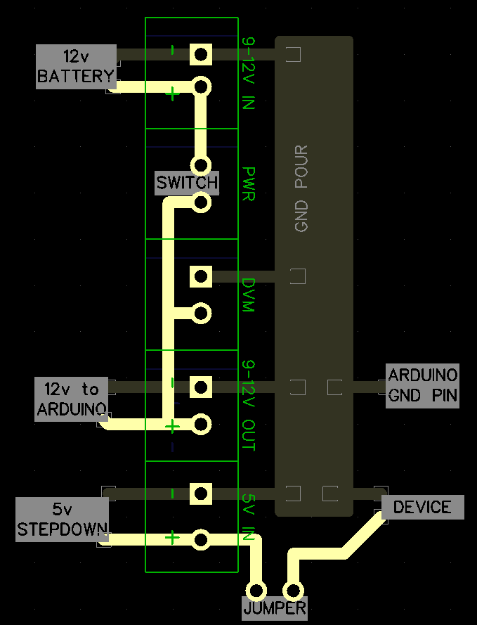
I have a 12v battery connected to my PCB. there is a switch on the + trace for on/off function and following that there is a volt meter to monitor the battery voltage. The traces then goes out of the PCB and splits into two leads, one goes into the Arduino using a barrel connector. The other goes into a 5v step-down and then back into the PCB for devices which require a more powerful 5v supply.
Now what about the ground for everything? Im useing a copper pour on the backside of the PCB which is connected to the GND pins on the arduino. But what about the -Neg leads/traces of the 12v and 5v? should they also be connected to the copper pour?
Its basically two pair of leads going from a battery. One pair into a volt meter, switch and then into the arduino. The other pair into the 5v step-down and powering on the more power hungry devices. But can/should the negative lead/gnd from the devices and 5v step-down be connect to the gnd on the arduino and the negativ lead on the battery?
Thank you
I was under the impression that it wasnt recommended to power the arduino useing the 5v pin, hence i tried to avoid it.
I also forgot to mention that I was planing to use a jumper to bridge the 5v pin and the devices, but when needed i can bridge the jumper to external 5v from the stepdown instead. Might be a bad idea.
Usually the grounds need to be connected together but sometimes not, and some power supplies have + and - outputs (relative to their ground) and you wouldn't want to "short" the negative voltage to ground.
If everything is "derived" from the same 12V power supply the grounds will be common at the power supply already and they can't have separate grounds.
Yeah i had the same idea that everything is connected to the same battery, so they should already have the same GND. was mostly concerned that voltage from battery or the stepdown found another way back to battery through the arduino and something very bad started to happen.
I'll look into having the step-down power the arduino and the devices as well
Made a quick illustration, nothing at fault here, besides not powering the Arduino using the step-down?