So I just got a chance to watch the Daze Cars video linked above & I get the tach / feedback now. So with the settings he shows by holding the button /encoder on the PWM generator he is able to get to a fraction of a % . What I'm wondering / thinking now is with the info of having a .10 --90 % fro, the generator will I have to get a couple of speeds for example , 200 rpm . 500 rpm, 1000 rpm & 1500 rpm will I have to tell the code/Arduino what the PWM % is for those rpm so it has some kind of info of what % correlates to what the rpm is ? Does that make any sense ? Would that be a " prescaler " ?
thanks
animal12
He does not use a Arduino and doesn't get any tach readings.
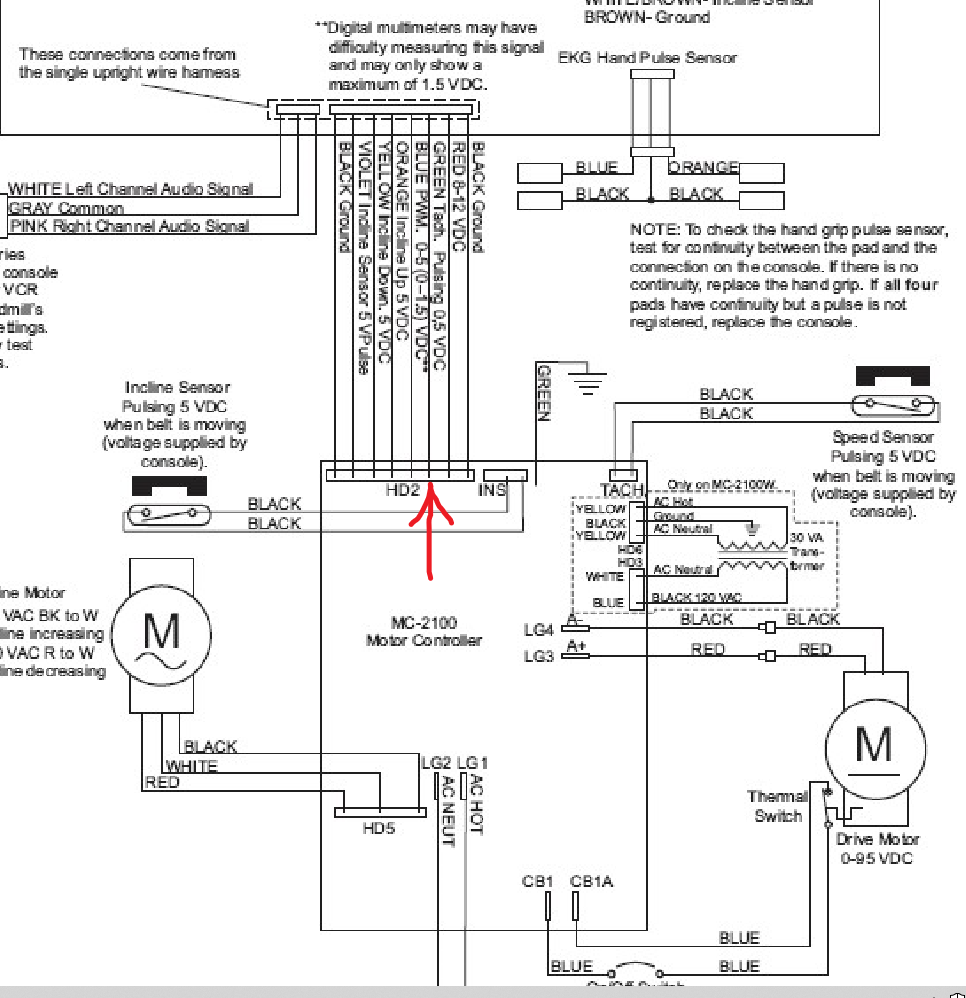
While guesstimating the RPM might be kinda sorta close. Wouldn't it make more sense to get the RPM directly from the tach output of the MC-2100.
I'd either use the PWM generator and guess your RPM and use a chart as he proposed in the video. OR Use a Arduino to do everything. No reason to use both.
I guess I asked wrong . I was only planing on using the PWM generator as a tool to find what the PWM % was at certain RPM's thinking I would need to know that come code time . MY whole plan is to use the Arduino for everything in the end result . Is there a way to get the RPM reading from the MC2100 ?
tha nks
animal
1 Like
Thanks , all the time I was looking at that diagram , I never saw that . I was looking at the PWM pins & the incline motor control pins .
thanks again
animal12
1 Like
SO does that pin I think its pin 6 put out a voltage every time the magnetic switch triggers on the
magnet on the driven wheel ? I think what my plan is is to have the arduino handle everything .
Like mentioned above the pwm generator was just for finding what pwm % = what rpm . after that the generator sits on the bench till I have another bad idea . Right now what Im really struggling with is how to make the keypad say 150, 500 , 1200 & so on when I press those numbers , like I'm trying to tell the arduino I want those # to equal the desired rpm ? Can someone please point me to a good simple keypad writeup thats in pretty simple terms if such a thing exists ?
thanks
animal
EDITED: to remove reply to chatGTP generated post.
Yes, 5v but the real question is... is that output raw or debounced. If it is debounced great you can use it directly to get RPM.
If it isn't you'll need to debounce it before using.
Here is one way:
char keyPress =0;

void setup() {
  Serial.begin(115200);
}

void loop() {
  static int desiredRPM;

  if (isDigit(keyPress)) { // Function from AVR/Libc returns true if parameter is a digit
    getDigit (desiredRPM);
    Serial.println(desiredRPM);
  }
  else if(keyPress == '#') {
    // We are done taking RPM Input
  }
}

void getDigit(int &num) {
  int thisDigit = keyPress - '0'; // convert ascii char and cast it to integer

  if (num == 0) {
    num = thisDigit;
  }
  else {
    num = (num * 10 + thisDigit);
  }
}
I've removed the nonsense AI reply and associated replies to that.
1 Like
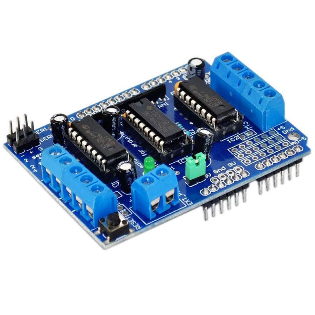
Thanks Hutkikz . While doing some reading last night I remember that I have a motor control shield & that has a pmw input I think , so wondering if that may be a way to go for testing to cut down on the risk of screwing up my MC-2100 ?
I've also been reading about using a Hall Effect sensor vs a Magnetic reed switch , from what I've read the hall effect sensor would be more accurate ? A issue I may have is that It may be a problem mounting a hall effect sensor as close to the spindle as I will need it in order to be able to read accurately . Maybe I can get my hands on a couple of just the reader part & mount that & run wires from it to the sensor board ?
thanks
animal
If that shield can work off of 20Hz PWM it might be ok for testing.
However the MC-2100 is designed to work with a reed switch and you will lose the built-in closed loop feedback support if you do not use one. You know I just realized that the reed switch output must be debounced for the closed loop to function properly. So you can use the signal directly without worry.
Thanks . Well It seemed like a good idea . I's totally forgotten about the 20 Hz . The shield only has Frequencies for channel 1 & 2 are:
MOTOR12_64KHZ
MOTOR12_8KHZ
MOTOR12_2KHZ
MOTOR12_1KHZ
Frequencies for channel 3 & 4 are:
MOTOR34_64KHZ
MOTOR34_8KHZ
MOTOR34_1KHZ
Back to plan A
animal
That board looks an awful lot like
or
http://wiki.sunfounder.cc/index.php?title=L293D_Motor_Driver_Shield
Those PWM channels directly connect to Uno Pins 4,6,7,12. If one could contrive to produce 20Hz PWM on one of those pins through hardware timers or soft PWM, it would work.
Unfortunately, 20Hz PWM only works on pin 9.(Timer 1 OC1A)
20Hz is 50000us. That's time enough to do a high resolution soft PWM on any pin:
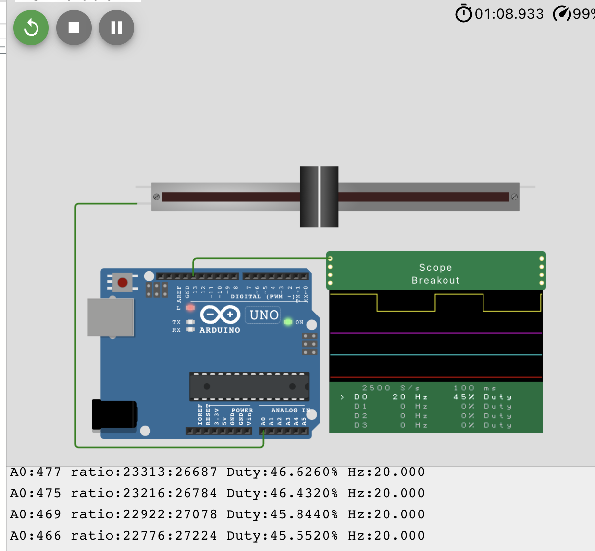
// https://wokwi.com/projects/365913963074043905
// for https://forum.arduino.cc/t/need-to-know-if-the-project-i-have-planed-can-be-done/1121026/37

const int ledPin = 13;
int onFractionPct = 10 ;
long onTime = 0;

struct ToggleTimerPin {
  uint8_t pin;
  unsigned long last ;
  unsigned long onTime ;
  unsigned long offTime;
  uint8_t state ;
} myLed = {13, 0, 10, 100, 0};

unsigned long period = 1000000UL *1000UL/ 20000;

void setup() {
  // put your setup code here, to run once:
  Serial.begin(115200);
  pinMode(myLed.pin,OUTPUT);
}

void loop() {
  updateSpeed();
  handleLed(myLed);
}

void updateSpeed(void) {
  static int lastADC = -1;
  int myADC = analogRead(A0);
  if (myADC != lastADC) {
    lastADC = myADC;
    myLed.onTime = myADC * period / 1023UL;
    myLed.offTime = period - myLed.onTime;
    Serial.print("A0:");
    Serial.print(myADC);
    Serial.print(" ratio:");
    Serial.print(myLed.onTime);
    Serial.print(':');
    Serial.print(myLed.offTime);
    Serial.print(" Duty:");
    Serial.print(myLed.onTime * 100.0 / period, 4);
    Serial.print("% Hz:");
    Serial.print(1.0e6 / period, 3);
    Serial.print(" \n");
  }
}

void handleLed(ToggleTimerPin & led) {
  unsigned long now = micros();
  if (led.state) { // on?
    if (now - led.last > led.onTime ) { // on -> off
 //     Serial.print('_');
      if (led.offTime > 0 ) {
        digitalWrite(led.pin, LOW);
      }
      led.state = 0;
      led.last += led.onTime;
 //     led.last = now;
    }
  } else { // off
    if (now - led.last > led.offTime ) { // off -> on
 //     Serial.print('+');
      if (led.onTime > 0) {
        digitalWrite(led.pin, HIGH);
      }
      led.state = 1;
      led.last += led.offTime;
     // led.last = now;
    }
  }
}
i think its the same board , I got mine from Amazon a few years back
animal
Oops, I read the schematic wrong and was off by one on those pins.
Per page 8 of https://cdn-learn.adafruit.com/downloads/pdf/adafruit-motor-shield.pdf
What pins are not used on the motor shield?
All 6 analog input pins are available. They can also be used as digital pins (pins #14
thru 19)
Digital pin 2, and 13 are not used.
The following pins are in use only if the DC/Stepper noted is in use:
Digital pin 11: DC Motor #1 / Stepper #1 (activation/speed control)
Digital pin 3: DC Motor #2 / Stepper #1 (activation/speed control)
Digital pin 5: DC Motor #3 / Stepper #2 (activation/speed control)
Digital pin 6: DC Motor #4 / Stepper #2 (activation/speed control)
The following pins are in use if any DC/steppers are used
Digital pin 4, 7, 8 and 12 are used to drive the DC/Stepper motors via the 74HC595
serial-to-parallel latch
The following pins are used only if that particular servo is in use:
Digitals pin 9: Servo #1 control
Digital pin 10: Servo #2 control
Those pins are connected as
| motorPins | PWM Channel | Pin |
|---|---|---|
| M1A/M1B | PWM OC2A | 12 11 |
| M2A/M2B | PWM OC2B | 4 3 |
| M3A/M3B | PWM OC0B | 6 5 |
| M4A/M4B | PWM OC0A | 7 6 |
| Servo 1 | PWM OC1B | 10 |
| Servo 2 | PWM OC1A | 9 |
Non-20Hz motors/motor controllers would work on any of them with Hardware PWM, but if you need the 20Hz PWM for the MC-2100, you need software PWM, either through something hand coded like above, or a library that does something similar.
1 Like
Thats kinda what I was thinking . Hopefully I will take care of enough loose ends in the next week or two that I will finally be able to bring all my Arduino & treadmill stuff over to the new place where I'm living now so I can finally try to get this project moving forward . I think my first step is to get a tach setup reading the pulses from the MC2100 to the Arduino . Then next I will try to get the keypad talking & go from there . Thanks for all the help so far folks .
animal
1 Like
Back looking at his , will I be able to power my Uno from the 8-12 VDC pin on the MC2100 ? The the 20x4 display will be powered by the 5 VDC pin on the Arduino .
thanks
animal
It is within spec so yes.
But be careful, The linear voltage regulator on the Uno was not the best choice they could have made. Basically because of the heat generated when the the input voltage is higher it causes the available current to be lower.
At 12 volts the regulator has to "burn off" the extra 7 volts as heat and then any extra load on the regulator( such as your display) causes it to heat up even more eventually letting out the magic smoke.
At 7v input power( the minimum allowed on the Vin pin) the regulator only has to "burn off" 2v which does not produce much heat leaving more current available for other peripherals.
A good rule of thumb is if you can hold your finger on the regulator for a period of time and are not getting burned it is probably Ok.
1 Like
Thanks , so it seems like the smart thing to do would to just power the Uno with a wall wart
Do I need to run a ground wire from from either pin 1 or 8 from the header on the MC2100 to a ground pin on the Uno since I'm using the PWM & RPM pins from the same header H2 ?
thanks
animal