Firstly, i am very new to this electronic stuff. Literally only got my beginners kit yesterday.
I hope my end project will be a small midi firing button. Press a button, send a midi command kind of thing.
But first i need help swapping out a button.
Please accept my apologies if i miss some information which may be required. Im learning.
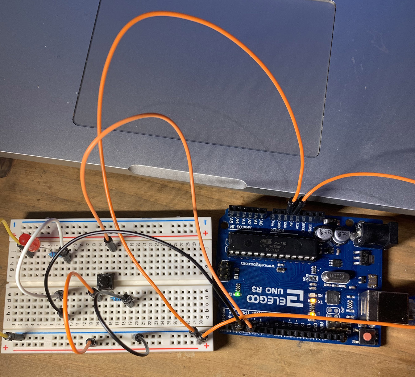
I'm using an Elegoo UNO R3 and if you look at pic1.jpg this is simple press a button, light an LED, and it works. But I'm trying to swap out the button on the breadboard for the button on pic2.jpg and i have no idea how to wire the pins as there are no wiring diagrams at all. All there is, is a + and a - on the back of the switch.
This is an 4 pin LED momentary normally open switch.
if anyone knows how i would wire this switch to replace the one on the breadboard I would be eternally grateful.
Also, a second question. Does this Elegoo Uno R3 have the USB programmable chip?
Although the current button has 4 pins, the pins on each side are connected to each other electrically, so really it only has two pins. The only reason for the four pins is so that it will have good mechanical support when soldered to a PCB. So you just need to wire the new switch exactly like the old switch. The connection to the 5V pin and the pull-down resistor on one switch pin, and the connection to Arduino pin 3 on the other switch pin.
Here's the relevant schematic (except it has the button connected to Arduino pin 2):
Ive now managed to wire up all four buttons, load the midi sketch and everything seems to be communicating.
Now, apparently comes the hard bit of flashing the board. I tried yesterday with a demo bit of code and failed miserably and its not working now either. lol.