I assume you are powering the NodeMCU via the USB connector. If so, I believe the relay power (VCC) should be coming from the "Vin" pin nearest the USB connector.
yes, I am powering the NodeMCU via the USB connector.
I tried to link the VIN pin of the nodeMCU to the power VCC relay but it doesn't work

If you have this board, shorting out the visible LED should get it working.
I advise using a separate 5V supply ... +5V connected to RY-VCC or JD-VCC, -'ve connected to GND.
No ground wire needed from the relay board to the NodeMCU.
The only connections from NodeMCU are 3.3V to Vcc , NodeMCU output pin to IN1.
Let me try this: A relay is just an electromagnet that controls a switch.
From the OP, the relay clicks, so it is working. As stated by CrossRoads
and raschemmel, the NO - C - NC terminals are connected only to the
switch, and the user must supply a power source for the LED and resistor,
because the relay module does not provide that. I see no power supply
for the LED.
Herb
dlloyd:
If you have this board, shorting out the visible LED should get it working.I advise using a separate 5V supply ... +5V connected to RY-VCC or JD-VCC, -'ve connected to GND.
No ground wire needed from the relay board to the NodeMCU.
The only connections from NodeMCU are 3.3V to Vcc , NodeMCU output pin to IN1.
So you advise me to power the relay with 5V? In this way I would have to have a power source for the nodemcu and another for the relay.. is it right?
So you advise me to power the relay with 5V? In this way I would have to have a power source for the nodemcu and another for the relay.. is it right?
Correct.
herbschwarz:
Let me try this: A relay is just an electromagnet that controls a switch.
From the OP, the relay clicks, so it is working. As stated by CrossRoads
and raschemmel, the NO - C - NC terminals are connected only to the
switch, and the user must supply a power source for the LED and resistor,
because the relay module does not provide that. I see no power supply
for the LED.
Herb
So what do you advise me to do?
The problem I have is this:
When I plug in the nodeMCU, the relay automatically turns on, and stays on... I currently connect the VU of the nodeMCU with the VCC of the relay...
It seems to be a problem at startup because if I plug in the connection (VU -- VCC) AFTER plugging in the nodeMCU, it works...
I'll show you two videos
VCC - VU disconnected during the boot ---> OK
VCC - VU connected during the boot ---> KO always ON
You can see from the attached pic, that the DS2 led is connected in series with the opto LED. As a result, 3.3V logic from the NodeMCU will not work unless DS2 and DS1 is shorted.

Why do we think it's a bad idea to use NodeMCU's "VIN" as 5V?
Proposed connections (DS1 and DS2 shorted)...
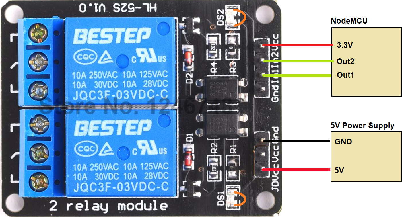
Ignore the part# on the relays (you have the 5V version).
dlloyd:
Proposed connections (DS1 and DS2 shorted)...Ignore the part# on the relays (you have the 5V version).
if possible I would prefer to avoid feeding the relay with another 5v cable. The way you say I will have one cable feeding the nodemcu and another feeding the relay. If that's the only way I'll do it, but I thought somehow I could use just one wire
runaway_pancake:
Why do we think it's a bad idea to use NodeMCU's "VIN" as 5V?
is it possible? I have already tried it, I connected VIN if nodeMCU with VCC of rele but it doesn't work
if possible I would prefer to avoid feeding the relay with another 5v cable. The way you say I will have one cable feeding the nodemcu and another feeding the relay. If that's the only way I'll do it, but I thought somehow I could use just one wire
Yes, its possible. Note that each relay would need about 70mA + IRLED current to operate. Not sure what your controlling, but note that you would also loose opto-isolation. Why not try a test with just one 5V supply, but temporarily jumper out an LED (i.e. DS1) and see if relay 1 operates correctly? EDIT: Shouldn't have to jumper out DS1 and DS2, Paul__B's wiring suggestions should work.
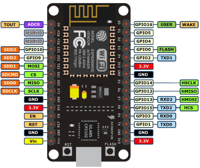
Which NodeMCU pin (D?) are you using?
D2 is a good general purpose pin. There are some peculiarities with the 8266's I/O, vis-à-vis their connection/states at boot up.
It is simper using these relay boards to connect "Vcc" to 5 V (but not the relay supply 5 V if this is separate) and the "IN" pin to the appropriate IO pin, rather than altering the board to make it sensitive to 3.3 V.
There seems to be some difference between the power connections of different versions of the NodeMCU, but in fact it has nothing at all to do with the power connections and dlloyd's suggestion would merely replicate the very same problem.
The actual problem is using "D8" (which is really GPIO15) as the control pin in this instance as it is causing the ESP8266 not to boot correctly. GPIO15 must be held to ground in order to boot the NodeMCU - you need to use another pin to control the relay. Similarly you must not pull D3 or D4 to ground.
I am currently using D0 - D7 to read the data from the 4x4 keyboard and the D8 connected to the IN of the Rele.
So, which one do I have to replace? Could I replace for example the D8 with the S3 or S2? And something else?
Thanks, guys!
Hi,
Can you please post a copy of your circuit, in CAD or a picture of a hand drawn circuit in jpg, png?
Thanks.. Tom.,.., ![]()

Hi,
I can't see a schematic.
I'm not sure with NodeMCU but D0 or GPIO1 and GPIO3 are Tx and Rx pins and may be used for programming and communicating to USB.
Tom.... ![]()
I have updated the image (i also put a link)