I have a circuit set up to detect water using a Darlington pair transistor and a S-R Latch, well actually I'm using 4 of them for redundancy. The latched outputs from the 74LS279N are tied the Duemilanove. My problem is that any little thing seems to set them off. If a large load in the house starts up (AC, fridge, cheep fluorescent light, ceiling fan etc...) it trips the circuits and set's off my code. Also if for any reason somebody touches the ground of the circuit like the mounting screw for the LCD or similar contact, it will trip the circuit just like the noise through the power supply.
If I run it off of a 9V battery to test, it's completely fine with the noise from the power in the house, but it's still sensitive to people touching the ground of the circuit.
I'm currently using a cheep 9V supply (Wall Adapter Power Supply - 9VDC, 650mA (Barrel Jack) - TOL-15314 - SparkFun Electronics)
I guess I can use a PC supply and run the 5V into a spliced USB adapter for a more regulated supply, but that's kind of bulky. But hey if that's the best option, then I'm in. But I don't know if that would solve the ground problem.
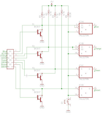
Here is the sensor circuit, just the same circuit 4 times over with the reset tied to all of the latches for easy resetting.
I am currently using the 5V pin from the board and using the ground pins as well. As for filtering.... um well i tried a .1uF cap across power by the IC on the breadboard with all of the sensors on it, I also tried a 47uF electrolytic across power on the same board. both have no effect on the problems. I added some 4.7uF caps across the sensor leads to slow down there reaction times and it helps absorb any transient voltage from them, but the original problem still remains of course.
Ok so I just ran it off of USB via my PC, and the noise from the celing fan still strips the sensors... I don't have a scope to see how small the spikes are, but I can't imagine there very big.
But this did solve the ground sensitivity problem. Now I can't cause problems by touching the ground at any point in the circuit like before.
The stupid ceiling fan or AC still cause issues.
I don't think it's grabbing noise like an antenna due to the fact that I can run the circuit off of a battery and it's perfectly fine. I can switch on & off anything I want in rapid succession in the house and it's fine. It's only when It's running off of a supply sourced from the 120V.
As to what's driving it.... well nothing most of the time. It's designed to detect water by bridging the 5V with the base through the water. So the majority of the time it's open and runs fine. It's just when noisy loads in the house happen it trips the circuit... I guess I can test the IC without the darlington plugged in to make sure it's the sensor and not the IC causing the latching...
I just had a thought. Could I slow down the rate that the input to the latch can rise?
What if I put an RC circuit with a time constant of a few tenths of a second in just before the latch input. That might take care of the spikes, but how would I keep it from building up slowly, as this setup could sit un-attended for weeks?
If I run it off of a 9V battery to test, it's completely fine with the noise from the power in the house
... but I bet the wires between power source and circuit are different in the two cases?
I have similar problems at two sites, and would love to learn more.
Could you do an experiment for me? Try the circuit with battery power, but with a wire as similar as you can easily arrange between battery and circuit? (Similar to the wire from your alternate transformer.)
I wonder if the transformer, under the load of your circuit is producing the same voltage as the battery? Might be interesting to compare. Don't see how it could matter, but who knows?
===
pwillard: You said "bias the bases"... could you explain the general principles and methods for this in a little more detail for us newbies?
===
Ground sensitivity: Was it the use of the PC's USB 5v that solved this? If you take those caps on the latch lines away, does it come back? Did you have a good connection between your circuit and Arduino ground from the start? I'd be interested in any thoughts people have regarding the sensitivity question, even though the problem had gone away for this project.
===
Why is it "okay" to wire the Q output from the latch together with the "set" input? I think I know, a short answer would probably do, but I just wondered...
===
Forgive a stupid question?... but the Darlington transistor sensors... those ARE photo-transistors, yes? And somewhere you have an LED and somehow the water routes the LED light to the photo-transistor when present? Or is it the other way around... no water, no light? Or something entirely different?
... but I bet the wires between power source and circuit are different in the two cases?
Yes they are, but I've run it with 4 different sources of power. The only one that seems immune is the battery pack.
I wonder if the transformer, under the load of your circuit is producing the same voltage as the battery? Might be interesting to compare. Don't see how it could matter, but who knows?
I checked at the Vin Pin, with the battery it's 8.7, and on the supply it's around 8.5. Both are right in the middle of the ideal range for the onboard regulator.
Ground sensitivity: Was it the use of the PC's USB 5v that solved this? If you take those caps on the latch lines away, does it come back?
If I run it off of the USB (via my PC) or on battery, the ground sensitivity seems to be gone. And when it's on the 9V adapter it dosen't seem to matter if the caps are there or not, it's still very sensitive to the ground being touched by anything conductive (myself included)
Why is it "okay" to wire the Q output from the latch together with the "set" input?
It's not. I think you are misunderstanding my lazy schematic. The Q outputs from the latch are not actually wired to the inputs... I just used some cat5 UTP cable for all my connections, so they appear to have the same names. Mostly I didn't label them correctly in the schematic.
... but the Darlington transistor sensors... those ARE photo-transistors, yes?
No, Darlington transistors are actually 2 'regular' transistors, better known as a 'Darlington Pair'. They are connected with the emitter of one transistor wired to the base of the other with a common collector. Just look at the schematic in the first post and you will see 4 of them with how they are set up internally. Basically you can do the same with any 2 transistors.