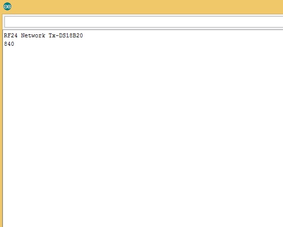
Here is the code I used for NRF24 with Potentiometer, when I tried running it, I only read one value on the serial monitor. I want to see a varying value whenever I calibrate it using a pot.
See the image attached below for the result I have.
Please correct my code if ever I've done something wrong.
Please help me.
#include <RF24Network.h>
#include <RF24.h>
#include <SPI.h>

int sensorPin = A0;    // select the input pin for the potentiometer
int ledPin = 13;      // select the pin for the LED
int sensorValue = 0;  // variable to store the value coming from the sensor


RF24 radio(8,53);
RF24Network network(radio);
const uint16_t this_node = 001;
const uint16_t other_node = 000;

const unsigned long interval = 2000; //ms
unsigned long last_sent;
unsigned long packets_sent;

struct payload_t
{
  byte senderID;
  float sens1;

};

void setup()
{
 Serial.begin(9600);
 pinMode(ledPin, OUTPUT);
  pinMode(sensorPin,INPUT);

Serial.println("RF24 Network Tx-DS18B20");
SPI.begin();
radio.begin();
network.begin(/*channel*/ 88, /*node address*/ this_node);
}

void loop(void) {
sensorValue = analogRead(sensorPin);

Serial.println(sensorValue);
                          // Check the network regularly

float sizeofpayload;
network.update();

unsigned long now = millis();

if ( now - last_sent >= interval )
{
last_sent = now;

byte senderID = 1;
float sens1 = (sensorValue);
payload_t payload = {senderID,sens1};
RF24NetworkHeader header(/*to node*/ other_node);
bool ok1 = network.write(header,&payload,sizeof(payload));
}
}
I really appreciate you for giving me that suggestion.
But it would be easy for me to use the network that I'm used to. This would be the answer to complete my project.
I hope someone could help me to solve my problem.
Thank you very much.
 /* YourDuinoStarter Example: nRF24L01 Transmit Joystick values
 - WHAT IT DOES: Reads Analog values on A0, A1 and transmits
   them over a nRF24L01 Radio Link to another transceiver.
 - SEE the comments after "//" on each line below
 - CONNECTIONS: nRF24L01 Modules See:
 http://arduino-info.wikispaces.com/Nrf24L01-2.4GHz-HowTo
   1 - GND
   2 - VCC 3.3V !!! NOT 5V
   3 - CE to Arduino pin 9
   4 - CSN to Arduino pin 10
   5 - SCK to Arduino pin 13
   6 - MOSI to Arduino pin 11
   7 - MISO to Arduino pin 12
   8 - UNUSED
   -
   Analog Joystick or two 10K potentiometers:
   GND to Arduino GND
   VCC to Arduino +5V
   X Pot to Arduino A0
   Y Pot to Arduino A1

 - V1.00 11/26/13
   Based on examples at http://www.bajdi.com/
   Questions: terry@yourduino.com */

/*-----( Import needed libraries )-----*/
#include <SPI.h>
#include <nRF24L01.h>
#include <RF24.h>
/*-----( Declare Constants and Pin Numbers )-----*/
#define CE_PIN   9
#define CSN_PIN 10
#define JOYSTICK_X A0
#define JOYSTICK_Y A1

// NOTE: the "LL" at the end of the constant is "LongLong" type
const uint64_t pipe = 0xE8E8F0F0E1LL; // Define the transmit pipe


/*-----( Declare objects )-----*/
RF24 radio(CE_PIN, CSN_PIN); // Create a Radio
/*-----( Declare Variables )-----*/
int joystick[2];  // 2 element array holding Joystick readings

void setup()   /****** SETUP: RUNS ONCE ******/
{
  Serial.begin(9600);
  radio.begin();
  radio.openWritingPipe(pipe);
}//--(end setup )---


void loop()   /****** LOOP: RUNS CONSTANTLY ******/
{
  joystick[0] = analogRead(JOYSTICK_X);
  joystick[1] = analogRead(JOYSTICK_Y);

  radio.write( joystick, sizeof(joystick) );

}//--(end main loop )---

/*-----( Declare User-written Functions )-----*/

//NONE
//*********( THE END )***********
Reciver
/* YourDuinoStarter Example: nRF24L01 Receive Joystick values

 - WHAT IT DOES: Receives data from another transceiver with
   2 Analog values from a Joystick or 2 Potentiometers
   Displays received values on Serial Monitor
 - SEE the comments after "//" on each line below
 - CONNECTIONS: nRF24L01 Modules See:
 http://arduino-info.wikispaces.com/Nrf24L01-2.4GHz-HowTo
   1 - GND
   2 - VCC 3.3V !!! NOT 5V
   3 - CE to Arduino pin 9
   4 - CSN to Arduino pin 10
   5 - SCK to Arduino pin 13
   6 - MOSI to Arduino pin 11
   7 - MISO to Arduino pin 12
   8 - UNUSED

 - V1.00 11/26/13
   Based on examples at http://www.bajdi.com/
   Questions: terry@yourduino.com */

/*-----( Import needed libraries )-----*/
#include <SPI.h>
#include <nRF24L01.h>
#include <RF24.h>
/*-----( Declare Constants and Pin Numbers )-----*/
#define CE_PIN   9
#define CSN_PIN 10

// NOTE: the "LL" at the end of the constant is "LongLong" type
const uint64_t pipe = 0xE8E8F0F0E1LL; // Define the transmit pipe


/*-----( Declare objects )-----*/
RF24 radio(CE_PIN, CSN_PIN); // Create a Radio
/*-----( Declare Variables )-----*/
int joystick[2];  // 2 element array holding Joystick readings

void setup()   /****** SETUP: RUNS ONCE ******/
{
  Serial.begin(9600);
  delay(1000);
  Serial.println("Nrf24L01 Receiver Starting");
  radio.begin();
  radio.openReadingPipe(1,pipe);
  radio.startListening();;
}//--(end setup )---


void loop()   /****** LOOP: RUNS CONSTANTLY ******/
{
  if ( radio.available() )
  {
    // Read the data payload until we've received everything
    bool done = false;
    while (!done)
    {
      // Fetch the data payload
      done = radio.read( joystick, sizeof(joystick) );
      Serial.print("X = ");
      Serial.print(joystick[0]);
      Serial.print(" Y = ");
      Serial.println(joystick[1]);
    }
  }
  else
  {
      Serial.println("No radio available");
  }

}//--(end main loop )---

/*-----( Declare User-written Functions )-----*/

//NONE
//*********( THE END )***********
Yeah sure, I will try work for it if I can, but I also need someone to help me out of this trouble I'm having with my codes.
thomas00:
Hi Clarkton,
Yeah sure, I will try work for it if I can, but I also need someone to help me out of this trouble I'm having with my codes.
Hi Robin,
Yes I'm already done doing that. I already made a small changes on the code. When I tried to remove the NRF24L01 on the circuit, the output is okay, but whenever I put NRF24 back, the result is like the attached image.
clarkton1:
Yes I'm already done doing that. I already made a small changes on the code.
Post the code that works and also post the code with the small change. It obviously was not the correct change. (And please list the line number(s) with the change).
Thank you for always responding to my questions.
I already know the problem with my program, after editing some changes on it, it's finally working.
You are always right with your "Two or three hours spent thinking and reading documentation solves most programming problems."