

not insert pictures of some code. use code tag. for Serial port results too
3 Likes
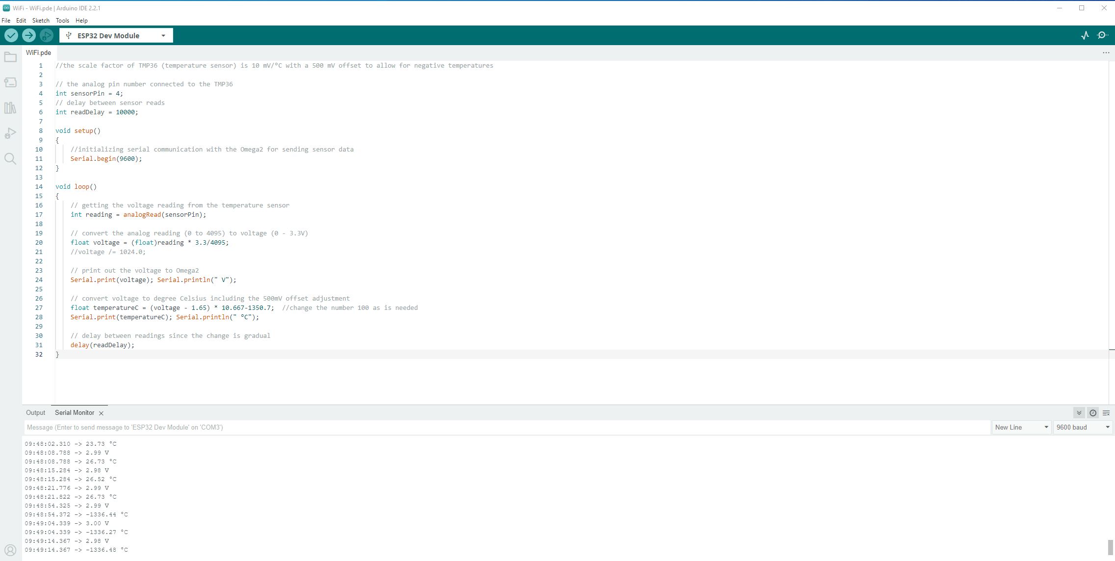
//the scale factor of TMP36 (temperature sensor) is 10 mV/°C with a 500 mV offset to allow for negative temperatures

// the analog pin number connected to the TMP36
int sensorPin = 4;
// delay between sensor reads
int readDelay = 10000;

void setup()
{
    //initializing serial communication with the Omega2 for sending sensor data
    Serial.begin(9600);
}

void loop()
{
    // getting the voltage reading from the temperature sensor
    int reading = analogRead(sensorPin);

    // convert the analog reading (0 to 4095) to voltage (0 - 3.3V)
    float voltage = (float)reading * 3.3/4095;
    //voltage /= 1024.0;

    // print out the voltage to Omega2
    Serial.print(voltage); Serial.println(" V");

    // convert voltage to degree Celsius including the 500mV offset adjustment
    float temperatureC = (voltage - 1.65) * 10.667-1350.7;  //change the number 100 as is needed
    Serial.print(temperatureC); Serial.println(" °C");

    // delay between readings since the change is gradual
    delay(readDelay);
}type or paste code here
Your
has not mentioned the aim or the issue you are seeing. There is a couple of photos or screen shots which most people ignore.
There appears to be a sketch to convert an analog reading to real voltage, and a resistor.
So ?
1 Like
Message (Enter to send message to 'ESP32 Dev Module' on 'COM3')

12:41:05.593 -> 1.33 V
12:41:05.593 -> 83.29 °C
12:41:12.599 -> 1.32 V
12:41:12.599 -> 82.40 °C
12:41:19.596 -> 1.32 V
12:41:19.596 -> 82.24 °C
12:41:26.556 -> 1.32 V
12:41:26.588 -> 82.24 °C
12:41:33.596 -> 1.32 V
12:41:33.596 -> 82.08 °C
12:41:40.592 -> 1.32 V
12:41:40.592 -> 82.40 °C
12:41:47.573 -> 1.29 V
12:41:47.573 -> 79.02 °C
12:41:54.592 -> 1.32 V
12:41:54.592 -> 81.84 °C
Not getting an accurate read ambient temperatures are far off and it is very slow to respond my ambient temperature is about 24 °C not 81.84
What sensor, and does it have a datasheet or instructions? A link to a website is fine.
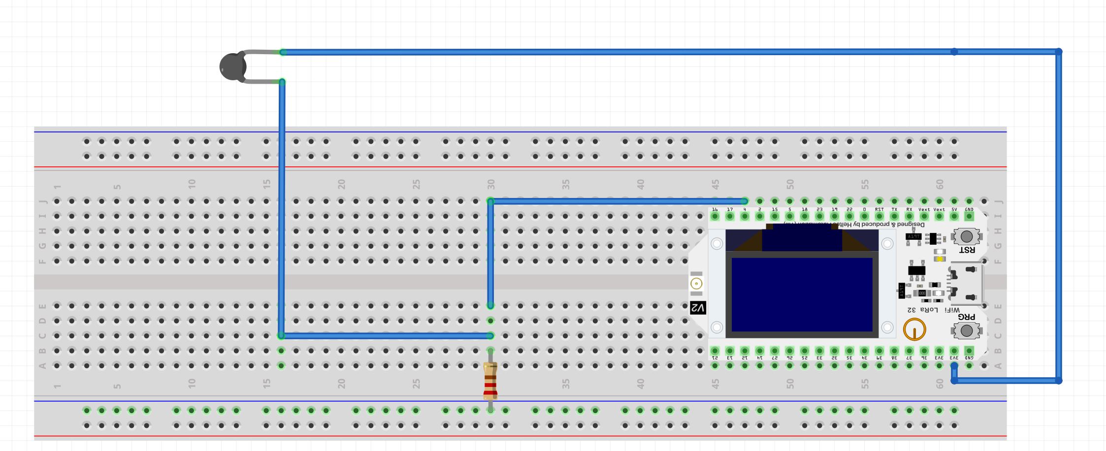
It might be better for you to draw out a circuit diagram of how you have it connected.
No link to the sensor custom made xfaacta
Kola resistance on the sensor without the circuit is 1096 OHM i can post a picture i will try to draw the schematics and post it to you guys.
the 3rd pictures states the sensor info under product parameters
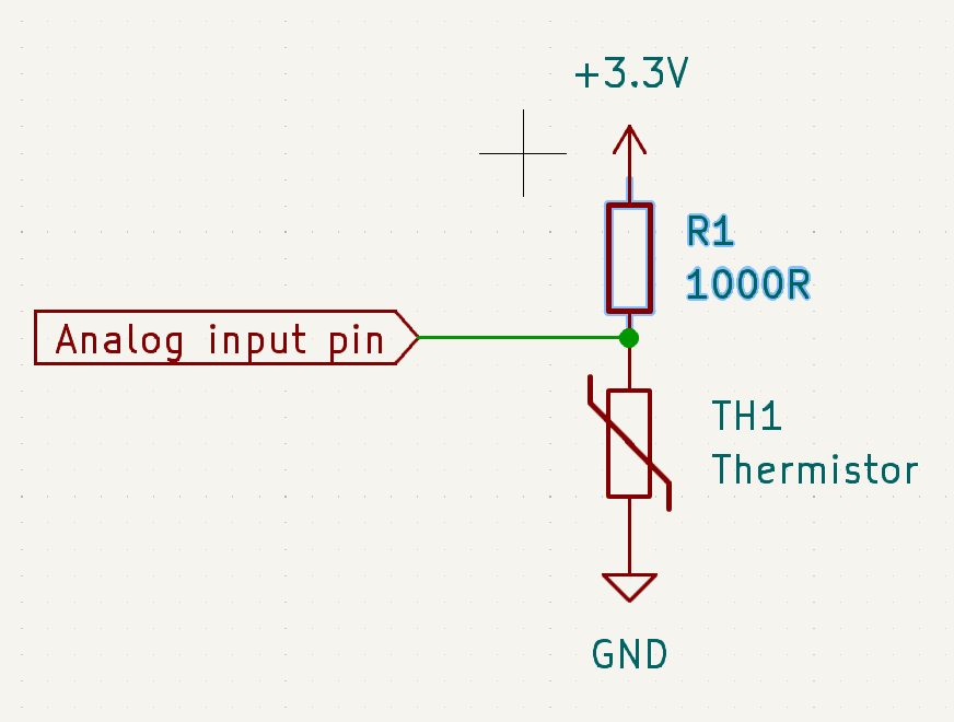
Do you intend to have this:
EDIT
I believe there is confusion there over the use of the power supply module at the end of the breadboard. Until this works, stick to powering the ESP from the USB and the circuit from the ESP pins.
post #5 this is wrong, delete this lines.
do you say somewhere that constant resistor is 10k Ohms ?
1 Like
No I do not say that somewhere using a 1K ohm resistor Kola
this is impossible. measure both, constant resistor and PTC.
schematic not correct, no GND. and pls don't use fritzing
Well until we know more I think you should use a 1k resistor, change it around to the diagram I provided where the resistor is acting as a pullup and the sensor connects to 0v. This is so when you end up with a finished product you are not sending the 3.3v supply out on some long wire to the sensor, to pick up noise like an antenna or short to something else. There's more to do in this regard once you get it working.
Please provide the measurements kolaha asked for.
2 Likes

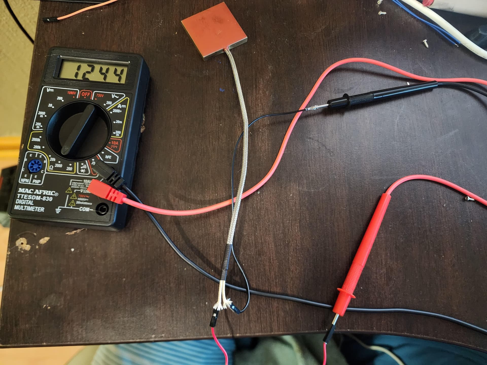
Constant and when you heat it up obviously it increases the hotter it becomes the more it increases got it to 1650 previously.
(and pls don't use fritzing)
Any alternative??
since this is no good to you?
KiCAD.
Try it.
You have your DMM setup wrong for resistance
Should be going to the Com plug i think.
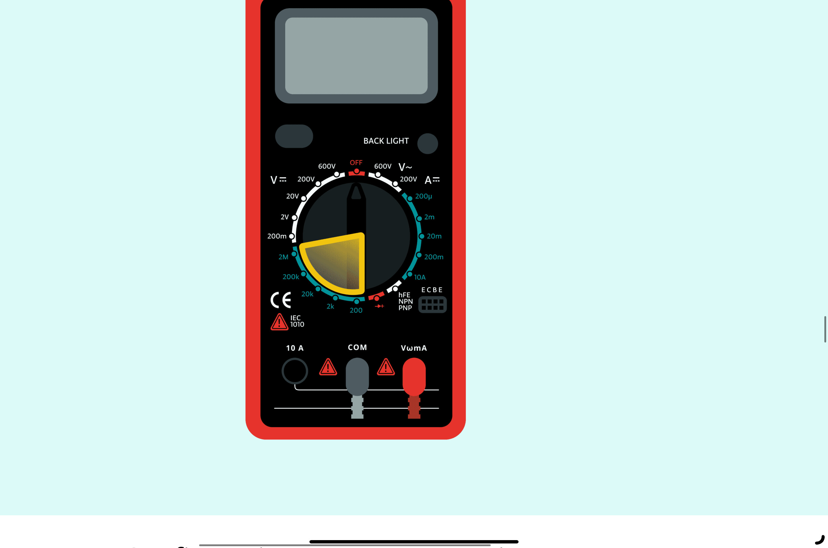
Read that………….
1 Like
Thanks I am new to this please bare with me and I am thankful for all the assistance.
Thanks v205