One wire DS18B20 reading +85°C, then -127°C and Arduino hanging up completely

The dallas temperature library blocks the program.

// sends command for one device to perform a temperature by address
// returns FALSE if device is disconnected
// returns TRUE  otherwise
bool DallasTemperature::requestTemperaturesByAddress(
		const uint8_t* deviceAddress) {

	uint8_t bitResolution = getResolution(deviceAddress);
	if (bitResolution == 0) {
		return false; //Device disconnected
	}

	_wire->reset();
	_wire->select(deviceAddress);
	_wire->write(STARTCONVO, parasite);

	// ASYNC mode?
	if (!waitForConversion)
		return true;

	blockTillConversionComplete(bitResolution);

	return true;

}

// Continue to check if the IC has responded with a temperature
void DallasTemperature::blockTillConversionComplete(uint8_t bitResolution) {

  if (checkForConversion && !parasite) {
    unsigned long start = millis();
    while (!isConversionComplete() && (millis() - start < MAX_CONVERSION_TIMEOUT ))
      yield();
  } else {
    unsigned long delms = millisToWaitForConversion(bitResolution);
    activateExternalPullup();
    delay(delms);
    deactivateExternalPullup();
  }

}

// returns number of milliseconds to wait till conversion is complete (based on IC datasheet)
int16_t DallasTemperature::millisToWaitForConversion(uint8_t bitResolution) {

	switch (bitResolution) {
	case 9:
		return 94;
	case 10:
		return 188;
	case 11:
		return 375;
	default:
		return 750;
	}

}

I assume the wiring is bad. The first is the best choice. The star is the less good wiring.

There’s a clue in there.

Auf diese Moment habe ich keine Schaltung bereit um die gebrauchte zeit zwischen request und temperature return zu testen.

Dear guys,

since my last post, the program luckily ran without any interruption flawlessly, so not destroying anything, which is very good. During I was away, I asked a person to look after from time to time if my “AliveErrorLED” still is blinking and it additionally does not write any strange temperatures on the OLED display, and surprisingly it worked the whole time!

Dear „Nick_Pyner“

Ad: “... I don't suppose there is any point in asking why there is incomprehensible crap about parasite power in your code then?”

For me, as said, all this was not crap in my code, because of the following: First I set a value / condition (e.g. no parasite power), but how shall I know if it really overtook this setting, so I subsequently ask the device: “Are you in parasite power?”, and I expect the anser to be “No.”. Only then I can be sure. So for this reason, this was necessary, and I did not regard it as “incomprehensible crap”, even I have understood this pice of code (written by anyone else than me).

Ad: “ I un- and re-plugged the power several times until it wrote a valid temperature”

With this, I wanted to find out if it ever will write the correct temperature with my modifications or not. But what’s so wrong with that? Everyone is doing repeated tests (often a 100 and 1000 times and more) to be sure, and I wanted to find out this with un- and replugging.

Ad “3. delivers said data when requested to do so by Arduino provided it has been given suffient time to prepare. IF NOT, it says 85 , which is plain english for "piss off! I'm not ready"

Yes, I think I wait now! Maybe all this then does need more than 2 seconds I have given as overall loop time, but for this, I have implemented that the “AliveErrorLED” will blink in a different pattern.

Ad “… your code is actually faulty, …”

Yes, that’s pretty clear, otherwise I would not ask for support here in this forum to help me, if everything would be perfect!! As said, with the hardware I can do for my own, or did you somewhere have read a question from me, like: “How do I operate the 7805 correctly?” No! I am always asking about software.

Ad “For all that, I would suggest you download the Hacktronics tutorial, add the extra sensor(s), and try it to prove the point.

THANKS FOR THIS LINK to this tutorial. For me, THAT IS SUPPORT NOW, so not just writing my code is so shit, but suggesting something concrete, namely: Get this 110% good code (which is tested and proven by a lot of people to be working I guess), and then “just” add the rest of my stuff. I will follow your recommendation. But not now, as the thing must operate ( = to keep things cool) say for another month. But after that, I will come back to your suggestion!

Dear “lastchancename”,

Yes, I know that the conversion takes 750ms, and I think I wait now enough in the setup as well in the loop as I changed the code according to the suggestions.

Dear „Nick_Pyner“ (again),

Some of my sensors are in TO92, others are in a metal full water proof case from the company “Adafruit” equipped with a 2m cable. I have 7 sensors connected to, as you can see, pin D2 to the Arduino. I do not use CAT cables, as some of the cables are given from “Adafruit”. So, as I described, the first 5 sensors are connected over a “normal 3 pin cable” each in “series” with a ca. 20cm cable, then the last 2 sensors are “Adafruit” ones connected with their standard cables (shorted to the length I needed.).

Dear „ buckfast_beekeeper”,

Ad “The dallas temperature library blocks the program.”

This sounds VERY good. I am not sure now, if this is also now through the library included in MY program posted above or not, but if not, I have to implement such a thing!

About the wiring: Yes, I have more or less the first “optimal” wiring, except for the last 2 temperature sensors, as said.

Many thanks guys,

bernd2700

You will - eventually, but I suspect it will take a long time...
And if, as you maintain, you really understand why that code is necessary, you are a better man than I, Gunga Din

No, I actually said quite the opposite..

and that is still the case. The fact that your gear works flawlessly when you are somewhere else says quite a lot about it.

I only suggest you use CAT5 cable if you are currently using junk out of the bottom drawer for the TO92 sensors - and having trouble. This is because it is commonly used, quality cable, and cheap. "Normal three pin cable" is as meaningless as it is fraught.

Dear "Nick_Pyner",

I think I cannot use CAT5 cable, since the pieces from one to the next of the first 5 temperature sensors is only approx. 15 - 20 cm but with only very little space! And the last 2 ones are waterproof from Adafruit with their used cabling defined from their production.

Tested today. Normal program 11 bits delay 375ms.


Always 494ms delay with no temperature change

    if (previousTemperatuurMillis + temperatuurIntervalMillis < millis()) {
      Serial.print("Tijd DS18B20: ");
      previousTemperatuurMillis = millis();
      sensors.requestTemperatures();
      fltTemperatuur = getTemperatuur(adres) + 0.05;// juiste afronding verkrijgen.
      strTemperatuur = printTemperature(fltTemperatuur);
      strTemperatuur += " ";
      //postJsonTemperatuur();
      //sensors.requestTemperatures();
      if (flgRun && fltTemperatuur != fltOldTemperatuur) {
        showScreenTemperatuur();
        fltOldTemperatuur = fltTemperatuur;
        postJsonTemperatuur();
      }
      Serial.print(millis() - previousTemperatuurMillis);
      Serial.println("ms");

With this in setup:

sensors.setWaitForConversion(false);


15ms without changed temperature and 23ms with changed temperature that must written on an oled screen.

Dear [bernd2700].
I am new to this forum, so I only read the description of your problems in this thread today. Since they are similar to mine, which I successfully solved, I will attach here my machine-translated (my English is poor) post from another local forum. I think it will be bananas for many of the colleagues here, but it may also be helpful to you and many others.

Arduino - how I saved my unstable 1-Wire 1Wire OW OneWire
How did I achieve this ? In a very simple way: I divided my "network" into parts, connected each of them to a different GPIO pin of my Arduino and, of course, adjusted the code accordingly.
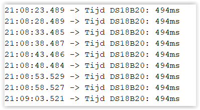
Simple right ? But it took me 2 years of constant trial and failure to arrive at this solution. A little about my installation: 1-Wire is used to collect temperature data from about 15 DS18B20 sensors located in various places in and around the house. It's a sizable installation with a weight of about 100m and a radius of about 20m (according to the terminology used in the studies below), working for several years, which became unstable after another expansion. Long-lasting, absurd or erroneous readings began to appear on some sensors (-273.15 or -127 or 85 *C and others, or lack thereof - depending also supposedly on the manufacturer of the sensor (original/clone)), generally leading eventually to the blockage of the entire bus. And worst of all: This phenomenon was unpredictable, occurred with varying frequency: from a few hours, to a few days, and only subsided after powering down the entire system for a few seconds (reset was not enough), so it didn't really yield to software support. First, of course, I started by replacing individual sensors - the ones that most often "died" on other copies, then I replaced the whole set of them, because this was the advice I read somewhere on the web (in addition to many other pieces of advice, boiling down to one: let go of the 1-wire, because you will not come to terms with this chimerical granddaddy anyway). It was only at this stage (like probably many) that I began to "study" the problems of 1-Wire, and I dug into the source study by Maxim-Dallas *1 (links at the end), which I recommend for study to anyone interested in this thread. From this study it became clear that the causes of the phenomenon could be various - I will not cite them here again referring to the source, and also that I had committed the "original sin", building a network in which the star topology prevails (this was the most convenient in my layout). At this stage, I began to maneuver the size, number, and position of pullUp resistors, as well as resistors that suppress individual lines. Some of these treatments seemed to improve the situation, but after a while - see the nature of the phenomenon above - they proved to be completely ineffective. The next move was to convert the topology of my network from the unrecommended star (3 arm), to the recommended line. The practical implementation of this was cumbersome and lengthy, and when it, too, finally failed to produce the desired result, I began to think about how to implement those online tips which said: let go ...
But here, too, problems arose. To make a long story short: Other digital sensors, such as BME/BMP280 or DHT (also sometimes unstable) and others fell off due to their excessive size or my requirement that they be airtight, and any analog sensors fell off after my experience with the LM35, which on longer lines (already on the order of 15 mb) did not work for me.
I was "on the dot." The full operation of my installation (about which at the end) depended on whether I personally could respond to an alert about a non-functioning temperature measurement system and turn off the power for a few seconds - disaster ! So I went back to reading the study *1. I paid attention to the thread described in the section Switched networks and the diagram:

obraz

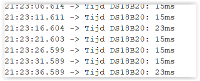
I decided to test this practically. I divided my 1-Wire line again, this time into 2 parts and connected both of them to the 1-Wire GPIO pin via the NO and NC connectors of an ordinary electromagnetic relay in such a way that they alternated between being connected to the input and being read by the master (controller) in an appropriately selected cycle. Such a (primitively) switched circuit worked and functioned without failure for more than 2 weeks, which gave me the grounds to not to look any further for a defect in sensors, wires, connections, configurations, etc. The next step was to write code using the tried-and-true 1-wire and ds18b20 libraries in a way that would support more than one 1-wire line, connected to a correspondingly increased number of GPIO pins, freeing me from the need to use other hardware enhancements and specialized controllers (also described in item *1). The solution turned out to be the creation of a library instance (fortunately, because I had another, but far less "elegant" solution in reserve). I split my 1-Wire once again, restoring it to its original form, but now as 3 independent lines connected to 3 GPIO pins. This circuit has been working for more than 2 months now without any interference, so I consider the concept and its implementation to have worked 100%.

Finally, I will recommend another study (link *2) treating the construction of 1-Wire, which I found recently, and in which, in addition to taking up and confirming some of the theses contained in *1, develops the very important issue of wires for the construction of 1-Wire and the details of their use. And then there are hints from my own experience: I confirm the sensitivity of 1-Wire lines to foreign electromagnetic fields. Usually in this context one talks about higher-power electric motors. I would add that this also applies to devices that produce weaker fields, such as relays. I suggest that 1-Wire lines should be at least 10cm away from them and also that wires for controlling relays or other inductive loads should not be run in the same twisted pair or harness as the 1-Wire bus data lines.

I wish all those interested in adapting this solution to their needs,
and to the inquisitive one who will call out: "This is a dig about which Copernicus already wrote in his blog !" I will say: it's a pity you didn't tell me about it earlier, because after all ... it's a waste of life for idle activities,
and to the purists who will state that "After all, this is no longer a 1-Wire network !" I will say: It is, and even 3 and it does !, so ... pity the life for idle activities,
and to those who find that they lack additional GPIOs, I say: the Mega 2560 has more than 60 of them (which is usually enough for a really big project), and costs ~ as much as 2xUno, Nano, etc., so ... pity the life for idle activities.

The attached very simple and short code supports 3 independent 1-Wire lines connected to 3 (digital) GPIO pins of any Arduino. What's obvious, you have to change the unique addresses of DS18B20 sensors in it (also stored in arrays if you prefer it), in an arbitrary (and obvious) way you can change the number of 1-Wire lines and pins used to support them - as many pins as lines, as well as the number of sensors in each line.

/*
    Many DS18B20 sensors on 3 lines 1-Wire connected to pins: 2, 11, 12.
    What is obvious, you need to change the unique addresses of the DS18B20 
    sensors, in any (and obvious) way you can change the number of 1-Wire 
    lines and the pins to support them (as many pins as lines), as well as 
    the pin numbers and the number of sensors on each line. 
    by zbylan@vp.pl , january 2023
*/

#include <OneWire.h>
#include <DS18B20.h>

// pin declaration for individual instances/lines
// deklaracja pin dla poszczególnych instancji/linii
OneWire onewire1(2);
OneWire onewire2(11);
OneWire onewire3(12);

DS18B20 Line1(&onewire1);
DS18B20 Line2(&onewire2);
DS18B20 Line3(&onewire3);

// here necessarily put the addresses of your DS18B20 sensors
// tu koniecznie wstaw adresy swoich sensorów DS18B20
byte adrRoom[8] = {0x28, 0xBE, 0x0, 0x7, 0xD6, 0x1, 0x3C, 0x9D};
byte adrPool[8] = {0x28, 0xBA, 0xCC, 0x7, 0xD6, 0x1, 0x3C, 0x42};
byte adrBath[8] = {0x28, 0x96, 0xF, 0x96, 0xF0, 0x1, 0x3C, 0xCE};

float tempRoom;
float tempPool;
float tempBath;

void setup() {
  while (!Serial);
  Serial.begin(9600);

  onewire1.reset_search();
  onewire2.reset_search();
  onewire3.reset_search();
  
  // sensor resolution declarations may be different for each line
  // deklaracje rozdzielczości sensorów mogą być różne dla poszczególnych linii
  Line1.begin(12);
  Line2.begin(12);
  Line3.begin(12);
}

void loop() {
  if (Line1.available() ) {
    tempPool = Line1.readTemperature(adrPool);
    tempBath = Line1.readTemperature(adrBath);
    Line1.request();
  }
  if (Line2.available()) {
    tempRoom = Line2.readTemperature(adrRoom);
    Line2.request();
  }
  if (Line3.available()) {
    // here read the temperature from the sensors on line 3
    // tu odczytaj temperaturę z czujników na linii 3
    Line3.request();
  }

  Serial.println(" ===============================================================");
  Serial.print("   tempBath: ");
  Serial.print(tempBath);
  Serial.print("   tempRoom: ");
  Serial.print(tempRoom);
  Serial.print("   tempPool: ");
  Serial.println(tempPool);
  delay(500); // needed only for friendly observation of the serial monitor
                     // DS18B20 is read asynchronously (not dependent on loop circulation time)
}

Note: The code was checked in Arduino compiler v.1.6.11 and v.1.8.12 (which is unlikely to matter) and with OneWire.h libraries version 2.3.5 and DS18B20.h by Mathias Munk Hansen, which may matter. If you have verified that it works correctly in another environment - please: let me know about it.

Links to the studies cited in the text:
*1 Guidelines for Reliable Long Line 1-Wire Networks | Analog Devices
*2 https://ntronic.pl/jak-projektowac-niezawodna-siec-1wire/ (PL language version)

P.S. As an aside: My entire project referenced here is a smart home installation built on an Arduino Mega 2560 with such autonomous functions as: control of central heating of the building (weather, daily and weekly) with pool water reheating and control of the solar system used also for heating the pool - hence such a large number of temperature measurement points (DSs), in addition to more than 20 different sensors to control other quantities, states and parameters, as well as stepper motors and relays controlling the gas boiler, pumps, valve drives, etc..., also carrying out many other functions in safety, comfort, control and information.

Regards - zbylan
zbylan@vp.pl
Don't look for me on social media. I don't hang out there (... it's a waste of life for idle activities :blush:).

Translated with DeepL Translate: The world's most accurate translator (free version)

2024.10.15
Regarding post #54 of September 2023 and subsequent posts, I must report a correction to my above post.
The cause of my sketch's compilation errors (three 1-wire lines on three processor pins) was the indication of the wrong library DS18B20.h
I don't know how this is possible, but my Arduino IDE points to DS18B20.h by Mathias Munk Hansen as the currently installed, while the compiler uses a different library that was previously installed on the system. This looks to me like some kind of library management error by the Aruino IDE.
By trial and error, I found the library DS18B20.h, with which my sketch compiles.

The relevant part of the above entry should therefore read as follows:
Note: The code was checked in the Arduino compiler v.1.6.11 and v.1.8.12 (which should rather not matter) and with the libraries OneWire.h version 2.3.5 and NOTE, because it definitely matters: DS18B20.h which is reported by the Arduino IDE as Unknown Version, which I obtained in a zip version (I don't remember the source), and which I can send you via e-mail (my e-mail address e-mail you will find at the end). If you have verified that it works correctly in another environment - please: let me know about it.
Regards zbylan@vp.pl

1 Like

Dear zbylan,

Thank you very much for your answer! I carefully red through your post, and there was one thing what I noticed: The electromagnetic topic! As already said a lot of times in my earlier posts, my 1-wire network is very short: The sensors are almost all in "line" configuration and the first 5 are just 15 - 20 cm apart (still in "line" !), the last 2 sensors are just approx. 3 meters away, that's my complete network, not more. So length should REALLY not be the problem. But the electromagentic thing could be the root-cause of my fails, and I thank you for the hint. I did not use shielded cables. However, what is strange is, that in summer the whole thing operates ok, and in winter at outside temperatures around 0°C , the 1-wire stuff sometimes fails. But the compressor with the little 3 phase motor (taking approx. 7A at 14V) ALWAYS will send out electromagnetic fields, in summer and in winter, so on the other side, this then also does not seem the root cause of my problem. But as one guy said: I should start again from the basis (from the "Hacktronics tutorial" with proven code) and then increase code again up to my needs. I did not do this up to now, because I am in a pause because of other things. But I will do it.
But what is your opinion to MY network: Just 7 sensors, alltogether ca. 3 meters apart, I think there is not the need to split the network to more GPIO microcontroller pins, is it?! I think it would not help in my case?!

Thanks,
bernd2700

Thanks for your

At the outset - sorry for the delay in responding.
About your net: It appears to be light and with a small radius (using terms from https://www.maximintegrated.com/en/design/technical-documents/tutorials/1/148.html ).
Although I'm not quite sure how to understand: "only 7 sensors, in total about 3 meters apart". , because it's not clear how far all of these are from the Master (your Arduino). But if indeed your entire network has both a radius and weight of a few meters and a line topology, then indeed there should be no problems with it. However, since the reality is that it is operating at the limit of stability, as evidenced by the summer/winter effect you described, i.e. the effect of changes in temperature, humidity, etc. on device timings or on physical interrupts - e.g. "cold solders" as suggested by colleague Nick Pyner, I think the cause of your problems, however, lies in the hardware (and not in the code), and implementing my suggestion can get you the fastest way to catch the cause of such a condition (and importantly: without interrupting the operation of the installation you have already built !). If you create a second line, to which you'll rewire, for example, your 2 airtight sensors, and run it together with the first line*, you'll find out the fastest way to find out if there are errors, and if so, where. Then you can decide what to do next, such as whether to rewire more sensors. If you would decide to build a second line, first check if your libraries will allow you to set up 1-Wire instances successfully. (If not, and you absolutely want to stay with your libraries, you can use the simple relay solution I wrote about previously on an ad hoc basis for testing). And one more thing: in accordance with what Nick Pyner wrote earlier, spare "a few cents" and make the 2nd line on the only wire currently recommended for 1-Wire: unshielded twisted pair (UTP) category 5e, running SIGNAL in 1 pair with GND. I don't elaborate on the details: everything is described in detail in the sources at the links I provided in the previous post (the 2nd material includes a drawing explaining what "signal in 1 pair with GND" means, if you had any doubts).

    • What is the shortest distance between the existing 1-Wire line and the motor you write about ? (Because maybe, building the 2nd line immediately significantly distance it from the motor ?)
      Regards

Thank you for this wake up call.

Dear zbylan,

First of all, thank you, too, for this great idea, to split the network into 2 parts with the 2, more far sensors, attached to a separate pin on the uC and the other closer 5 ones on another uC pin, in order to find out which one is the “guilty” part. As I have said already I definitely will also follow Nick Pyner’s - at the end concrete - suggestion, to use the proven code from “Hacktronics” as a new starting point for my software and and do my add-ons one after the other.

As I already have written, “The sensors are almost all in "line" configuration and the first 5 are just 15 - 20 cm apart (still in "line" !), the last 2 sensors are just approx. 3 meters away (2 meters out of the 3 are in "line", so one common cable and the approx. last meter divides the 2 sensors, so being each approx. 1 meter away from the common point).

As said, there is no way to do CAT5 cabling or similar, because in the first line with the 5 sensors, I simply do not have the physical spacing (even the connectors would be much too big!) and 2nd line with the other 2 sensors must have the given water-resistant cabling, so also there I cannot change the cable.

But as said: Following and combining (how to do that, I will see, hopefully) both recommendations (from you: Make two 1-wire lines to different uC pins, and from Nick Pyner: start with the proven “Hacktronics” code), should bring me a step further. But this will take quite some time.

By the way: The shortest distance between a part of a 1-wire network “crossing” the motor are maybe 2 cm, as one of the temperature sensors is directly connected to the hot output copper metal “tube” of the compressor in order to measure the hottest point in the whole system.

Thanks and good evening,

bernd2700

This topic was automatically closed 180 days after the last reply. New replies are no longer allowed.

Dear guys,

It's September and I need to solve the issue written in the headline.
Unfortunately the topic was closed due to an automatic time-out, so I have to open up a new thread.

I re-read the old stuff, and now I wanted to impement the very promising solution from "zbylan", but all it does is writing me errors.

The code I tried to upload is:

/*
Many DS18B20 sensors on 3 lines 1-Wire connected to pins: 2, 11, 12.
What is obvious, you need to change the unique addresses of the DS18B20
sensors, in any (and obvious) way you can change the number of 1-Wire
lines and the pins to support them (as many pins as lines), as well as
the pin numbers and the number of sensors on each line.
by zbylan@vp.pl , january 2023
*/

#include <OneWire.h>
#include <DS18B20.h>

// pin declaration for individual instances/lines
// deklaracja pin dla poszczególnych instancji/linii
OneWire onewire1(2);
OneWire onewire2(11);
OneWire onewire3(12);

DS18B20 Line1(&onewire1);
DS18B20 Line2(&onewire2);
DS18B20 Line3(&onewire3);

// here necessarily put the addresses of your DS18B20 sensors
// tu koniecznie wstaw adresy swoich sensorów DS18B20
byte adrRoom[8] = {0x28, 0xBE, 0x0, 0x7, 0xD6, 0x1, 0x3C, 0x9D};
byte adrPool[8] = {0x28, 0xBA, 0xCC, 0x7, 0xD6, 0x1, 0x3C, 0x42};
byte adrBath[8] = {0x28, 0x96, 0xF, 0x96, 0xF0, 0x1, 0x3C, 0xCE};

float tempRoom;
float tempPool;
float tempBath;

void setup() {
while (!Serial);
Serial.begin(9600);

onewire1.reset_search();
onewire2.reset_search();
onewire3.reset_search();

// sensor resolution declarations may be different for each line
// deklaracje rozdzielczości sensorów mogą być różne dla poszczególnych linii
Line1.begin(12);
Line2.begin(12);
Line3.begin(12);
}

void loop() {
if (Line1.available() ) {
tempPool = Line1.readTemperature(adrPool);
tempBath = Line1.readTemperature(adrBath);
Line1.request();
}
if (Line2.available()) {
tempRoom = Line2.readTemperature(adrRoom);
Line2.request();
}
if (Line3.available()) {
// here read the temperature from the sensors on line 3
// tu odczytaj temperaturę z czujników na linii 3
Line3.request();
}

Serial.println(" ===============================================================");
Serial.print(" tempBath: ");
Serial.print(tempBath);
Serial.print(" tempRoom: ");
Serial.print(tempRoom);
Serial.print(" tempPool: ");
Serial.println(tempPool);
delay(500); // needed only for friendly observation of the serial monitor
// DS18B20 is read asynchronously (not dependent on loop circulation time)
}

I have installed the OneWire Library "2.3.7" also by "Jim Studt, Tom Pollard" ..., (Zbylan has 2.3.5) then I have the "DS18B20" library "1.0.0", also, as Zylan by "Mathias Munk Hansen", the Arduino surface is "1.8.13".

It writes errors like:

warning: invalid conversion from 'OneWire*' to 'uint8_t {aka unsigned char}' [-fpermissive]
DS18B20 Line1(&onewire1);

In function 'void setup()':
sketch_from_Zbylan_More_1wire_temp_sens_on_3_Arduino_GPIO_lines:43:9: error: 'class DS18B20' has no member named 'begin'
Line1.begin(12);
^~~~~

error: 'class DS18B20' has no member named 'available'
if (Line1.available() ) {

error: 'class DS18B20' has no member named 'readTemperature'
tempPool = Line1.readTemperature(adrPool);

But Zbylan said, he tested his script, so I assume it basically works (except as he writes changing the address of the sensors or GPIO pins).

Do you guys have any idea how to can solve this and successfully test Zyblans script on my Arduino Nano?

Thanks a lot for your support,
bernd2700

Please flag the original thread....Describe why want it open, then you can continue your discussion.

1 Like

Dear theeccentricgenius,

Thanks for your answer! I think with "flag" you mean, I shall copy the link to the original topic?!

I would like to re-open, since I did not have time to follow up the suggestions from the forum people, and I did not remember that a topic will be closed after 6 months (in other forums I did not experience such an automatic time-out).
Now, I wanted to concretely apply a code from a forum user, but in my case it does not work, although, according to the user, as far as I understand it at least, should work.

Will you then re-open that orig. topic for me?

Thanks a lot,
bernd2700

The functions being called seem to be for a different sensor:

Which uses these function calls (members):

Line1.begin(12);
Line2.begin(12);
Line3.begin(12);
.
.
tempPool = Line1.readTemperature(adrPool);
tempBath = Line1.readTemperature(adrBath);
tempRoom = Line2.readTemperature(adrRoom);

Found in this library:

Dear xfpd.

Thank you for answering! Ok, I read your interesting comment, but for me it's very strange, because in the code, it clearly says "DS18B20" in more places. - Hmmm! So, this does mean, the code is not appropriate for me?
Are there maybe opinions from others? (Because you write "seem", so could it be, that it is really for the DS18B20 but some libraries are missing or similar? I don't know. So what to do? Any suggestions?

Thanks,
bernd2700

I write "seem" because I know nothing (memory fails) and reference my way through life (with ddg.gg). : )

It is good of you to verify.

I understand your doubting my response, and further, your code can still be true if a library with the calls for "x.begin()" and "x.readTemperature()" (and all the other function calls) exists for the DS18B20. Many libraries exist with the same title and device, so I expanded my search to the function calls within the code. My searches for those function calls pointed to the Adafruit sensor.
[edit 1]

This is a sketch from Arduino.cc's reference to Mathias Hanson (Matmunk) DS18B20 library:

#include <DS18B20.h>

DS18B20 ds(2);

void setup() {
  Serial.begin(9600);
}

void loop() {
  while (ds.selectNext()) {
    Serial.println(ds.getTempC());
  }
}

Notice how the DS18B20 is initialized:

DS18B20 ds(2);

And then see how the temperature is read:

    Serial.println(ds.getTempC());

[edit 2]
For your DS18B20, it seems (!) DallasTemperature.h is the preferred library by a known library author, and would only require minor edits to your sketch:

Sorry, can't not a mod or leader.

Flagging is clicking the flag button at the bottom of the topic or post.
image