But you are testing the TIMSK1 mask flags, not the TIFR1 interrupt flags. Is anything changing TIMSK1?
Oops. I missed the ~ sign on the bits -- all the conditionals are constantly true, so the first if(true) obviates the elses.
I meant it is difficult to figure out what your code does without closely reading it and the datasheet on the registers and their bits. You can describe the intent, but some bits or logic aren't set up correctly.
I'd advise slowing it down (slower PWM, different OCR1x values) and simplifying the logic (one output, less interrupts) until it works, and then re-enabling bits one at a time in order to locate the errors.
Edit to add: I particularly like the Microchip online reference docs because you can link right to a register:
Hey man,
Still struggling to get around this thing.
Maybe you could kindly enlighten more in this path of embedded system.
So I need the pwm signal of around 31KHz to go through my motor drive, so not compensable..
However, in the past days I have made some progress.
Approach changes a bit:
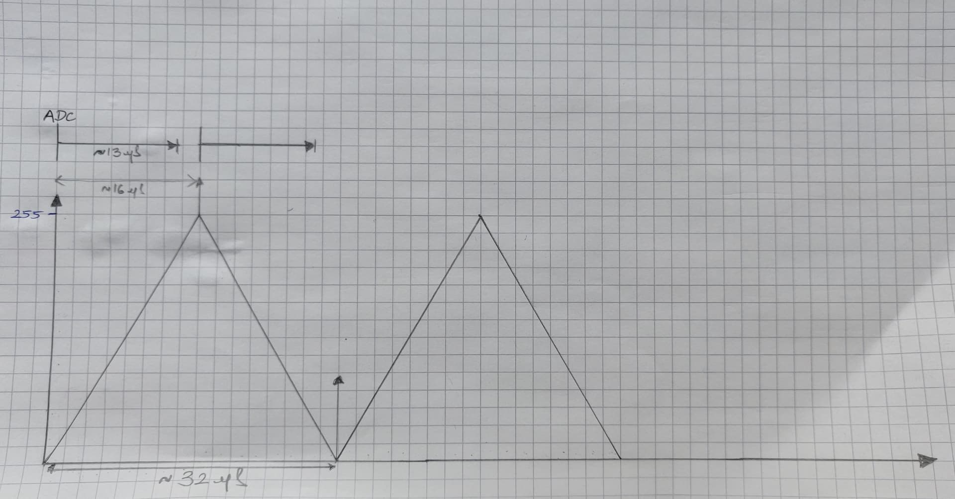
So I need to continously update my OCRnX registers during my Interrupts (TOP & BOTTOM), which basically controls the motor speed (dutycycle). My ADC sampling rate is about ~76KHz (good according to Nyquist theorem). I am currently sampling 1V continous DC signal (whose adc value should be around 51). This adc value should continously update my OCRnX values to have a constant duty cycle of 20% (DW about the maths, I checked it;) with a frequeny of 31KHz. This PWM frequency shouldnt really affect anything since this is a parallel generated activity, although the duty cycle should change if I change my analog input to lets say a sine wave. Hope youre with me until here. Here's a timing diagram to help understand better:
"ISR set" are the flags that I set to basically help my void loop do the OCRnX updates and Serial.print(ADCReadings) to look at them visually in the monitor. (Maybe look at the code below to understand better)
I am (hopefully) using all the correct register for my ADC & PWM, but have a value of 3 continously even when I differ my incoming analog input signal (V range & frequency). I have my input at A1, with ADC in the auto-trigeering mode with the source at the Capture_event
I have an 8-bit ADC value which i store it in my 'ADCReadings' variable and continously pass it to my serial monitor during the interrupts using flags (ICF1) in my main void loop.
The code below has only one interrupt set at Capture_event, the rest is formatted out as the logic stays the same in the other interrupt.
Hoping to get some positive assists.
Cheers mate!
Is this wired up to anything? Pin 8/ICP1 in particular?
What triggers the TIMER1_CAPT_vect where it overwrites ICR1 with TCNT1?
Why does the ADC have to be synchronized with the PWM? Are you trying to measure a response to the PWM pulse in phase with the PWM? If I hooked up an RC filter from OC1A or OC1B to A1, would that simulate the intended use? Are you trying to set the upslope and downslope OCR1x values differently
based on the ADC?
This just copies the top 2 bits of ADC. Maybe you want:
Wirings are as follows:
A1 with my Analog Input source (Analog Discovery 2) in a voltage divider circuit connected to the ground with the UNO board.
Pin 9 & 10 to two different circuits just to test the flow of the PWM signals. I've also got 2 point oscilloscopes to check my PWM signals in both of those circuit. So basically Pin 8 is empty.
The Interrupt flags and masks (ICF1 & ICIE1) trigger the TIMER1_CAPT_vect whenever TCNT1 matches the ICR1.
So the purpose of synchronization is to have continuous digital points (with some delay ofc) which updates the OCRnX registers based on our analog signal to control the speed(Duty cycle) of our DC motor based on that analog signal from my PLC Drive. Freeing up the OCRnX is my main purpose so I could use it for continuous duty cycle updates. 2 ADC conversions per PWM signal.
But the manual states that only ADCH must be read if a 8-bit value is expected.
The thing is, I have some ADC readings (175, 198, 4 ...) which repeat themselves even when I apply a const DC signal. The sole problem is my ADC result tracing which is messed up on my serial monitor and which in turn messes up my OCRnX values. Everything else seems working.
Yes! That is exactly my next step, although my both PWM signals are inverse of one another.
Still Doesnt ring a bell.
So i was wondering if my serial communication between the Arduino and my lappy is not adequate. However, even when I don't print my ADC values, it shouldn't be a problem as well as the duty cycle is varying if I have a sine wave or should be const at 51(OCRnX) when I supply 1V DC supply. Doesn't work either.
Other things is, the TIMER1_CAPT_Vect isn't getting initiated, so i only have one interrupt running which is the one at OVF.
Cheers.
Solved it brotha!!!
Had to manually start my adc conversion in the main loop and also did not consider the ADC reference voltage.
Altho I dont understand what should be my buffer size for the ADC values.
you got any clue?
Cheers!