I am doing a project for my ev and using nano every.. tests have successfully concluded with laptop and USB connection. Now, I want to use the 12V supply (usually 13.5V-14.4V) of the car (this is coming from DC DC converter of the car from 48V to 12V) to power up the arduino so I can keep it connected and place it in the dash. I searched and saw nano can take Vin upto 15V but also saw some randomly blowing so I want to know what would be the best to do? Every pin seems to use 5V in IO pins so I guess we have to use 6V or above. What is the total current it might pull from VIN? Is it 40mA per pin? I plan to use almost all pins for the car functions, 7-8 already used just for TFT display.
Unlike the classic Nano, the Nano Every uses a switching input voltage regulator and can take an input voltage of 21v.
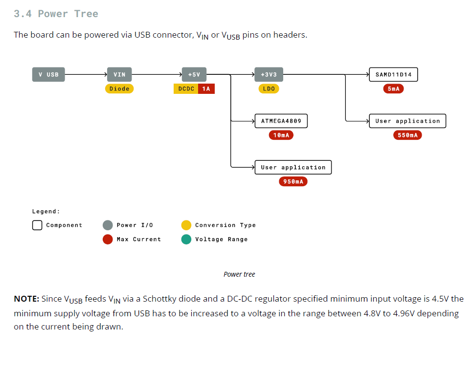
You should review the specifications for the Nano Every, but I think that the total current through the regulator can be up to 550ma, but the recommend max is 200ma.
Current per I/O pin is 20ma.
What is the total current it might pull from VIN? Is it 40mA per pin? I plan to use almost all pins for the car functions, 7-8 already used just for TFT display.
In general, an Arduino is not a power supply.
You may want to provide a schematic of how you plan to connect everthing.
Thanks. i will check the datasheet again. I was searching and mostly arduino nano things pop up and I supposed they are mostly same.
Yes, I understand arduino is not a power supply. I am using the pins as either inputs or outputs so it turns on optocouplers to turn on 12V systems and indicate that in a screen. I just wanted to know the max current it can bear if I needed to a voltage divider.
I haven't created the schematic but its like normal.. use battery for Vin Gnd and then use pins as IOs and some dedicated pins connect to a TFT display.
I connected to a 13.2V dc converter from car which turned on the arduino but the screen somehow was just a white screen. It didnt smoke anything until this time as I tested again with computer USB and it was working fine till then.
Then, I got overly excited to try another supply which turned on when the key was turned on but alas, I smoked the arduino (nano every). Later, I checked with voltmeter and it spiked to 20V for a second and then went back to 13.2V (maybe that was unregulated) and I guess it generated more current during this time making it smoke. Lesson learnt.
I am still wondering why it didn't turn on the screen normally first.
Now, I am testing another nano every with a 9V battery and it works fine. Next I am going to try with a 7812 regulator and see if that 12V will work. anyone done that?
Ah, 7812 also didn't turn on the screen (just white).
Come to think of it, I think the issue with car battery is that the same ground is shared across devices so that is probably not a good idea? powering with computer or a 9V battery has a separate ground. Anyone know a solution here? I don't want to add a separate battery as it will need replacing every now and then.
Thanks.. I am also reading so much threads now.. do we need the bypass capacitors in the input/output ? saw some suggestions.. i will try to get the 9v one and see..
An output will deliver the current that the load asks for. It’s just that if that current is high, the output won’t last long. So you better read: 20mA max.
This is not absolute. It’s quite possible to power a small circuit from your Arduino. Small is a relative term. For a UNO small is a few LEDs. The Nano Every is more powerful, but as always: stay away from maxima.
This picture has an error: V USB not connected to VIN, but with a Schottky diode to +5V.
Another thing you need to know: if your Nano Every is connected to your car and to your PC at the same time, and the car is turned off, the Nano Every will try to supply your car from USB. Multiple boards have died this way.
Thanks for your detailed information. I am still learning...
Can nano every turn on a 5V relay? Normally, I found that 5V relays need around 80-90mA to turn on, so not entirely sure if arduinos are able to do that. Otherwise, I just need to turn on output and do something or read input (coming from optocouplers) and show something on the screen.
I have not tried with both car and computer.. Its either one. My goal is to be able to put arduino in the car so need the cars DCDC converter (12V) to power it. I am using computer to test right now as it turns on the screen without issues. I need to find out how to do this properly with car 12V.
AEC-Q100 is basically the automotive standards. There are several groupings etc that address many parts of the electrical/electronics portions including test standards. I have not looked at them for several years and they are a dynamic group of specifications. There are many ways of isolating the transients other then opto couplers, they are expensive. You do not want wires connected to processor pins to connect directly to the car, you need to isolate them. The only exception is ground for power. Resistors etc are much more cost effective solution. You will find ground lift, reverse battery etc in there. By chance does this fall under the "42 volt" electrical system? My last years were in that area.
The 12V decision for convenience items was made about the time I retired. I have patents in that area, the most fun was running 12V headlamps on 42V, it was accomplished. When they failed it appeared as a big flash bulb.